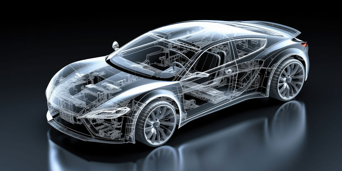
When a vehicle is involved in an accident, extreme forces are placed upon the design characteristics of the structure, as well as all related and attached system components. This energy management of the collision forces is what began the need for technical training and the formation of I-CAR. And the importance of this training over the years has set the United States and Canadian collision industries apart from most other countries in the world.
I’ve had the opportunity to visit many other countries and have discovered a lack of understanding of advanced concepts at the technician, owner, manager and, especially, insurer level. And without the presence of a training program designed for participation by all industry segments, there seems to be very little training available. Hence, repair quality suffers.
Today, when we as repairers are involved in the process of returning a vehicle back to pre-loss condition as it relates to function and appearance, we must be very keen to determine if all damages caused from the accident are being repaired. And this can be very difficult to impossible by only an initial inspection, since damages can be “masked” by other parts and appearances. This places an additional responsibility on the repairer and even the technician to identify these supplementals. It also requires a high level of knowledge by all parties to understand what’s required in the repair or replacement procedure of all the automotive systems.
Today’s suspension systems are no different. I’ve taught hundreds of technicians at diagnostic and alignment classes and seminars during the last 15 years. And I’m still amazed at the lack of understanding regarding how wheel alignment angles tell you the story of damage to suspension parts.
Since frontal collisions are the most common and since a high percentage of today’s front suspensions are McPhearson Strut, it makes sense for us to concentrate here on McPhearson Strut systems. But first, let’s do a quick review of what’s out there.
Back to Basics
Three basic front suspension systems are used on vehicles and all provide the same purpose: to handle the forces of braking, acceleration, normal driving and turning during vehicle operation.
These three basic systems are:
- Short Arm – Long Arm System (SALA or SLA);
- McPhearson Strut;
- Twin I-Beam.
Let’s take a closer look at all three:
1. SLA – These systems have the wheel spindle or knuckle mounted between two arms, called control arms. The top one is shorter than the bottom. These arms can be shaped as an “A” or “Wishbone,” which is where we got terms such as “A-Frame” and “Wishbone Suspension.”
This suspension was the most commonly used type in the United States prior to the changeover to unitized vehicles in the early ’80s. Even today, these systems or variations of this system are used, in part, because they can carry more weight. By design, engineers can simply increase the size and strength of each arm to handle additional weight requirements. Today, aluminum and other alloys are often used with this design to lower the weight of the suspension system to the vehicle. Since this design holds the shock absorber and spring between the two arms, the aerodynamics of the front of the vehicle often can be lower than McPhearson Strut systems.
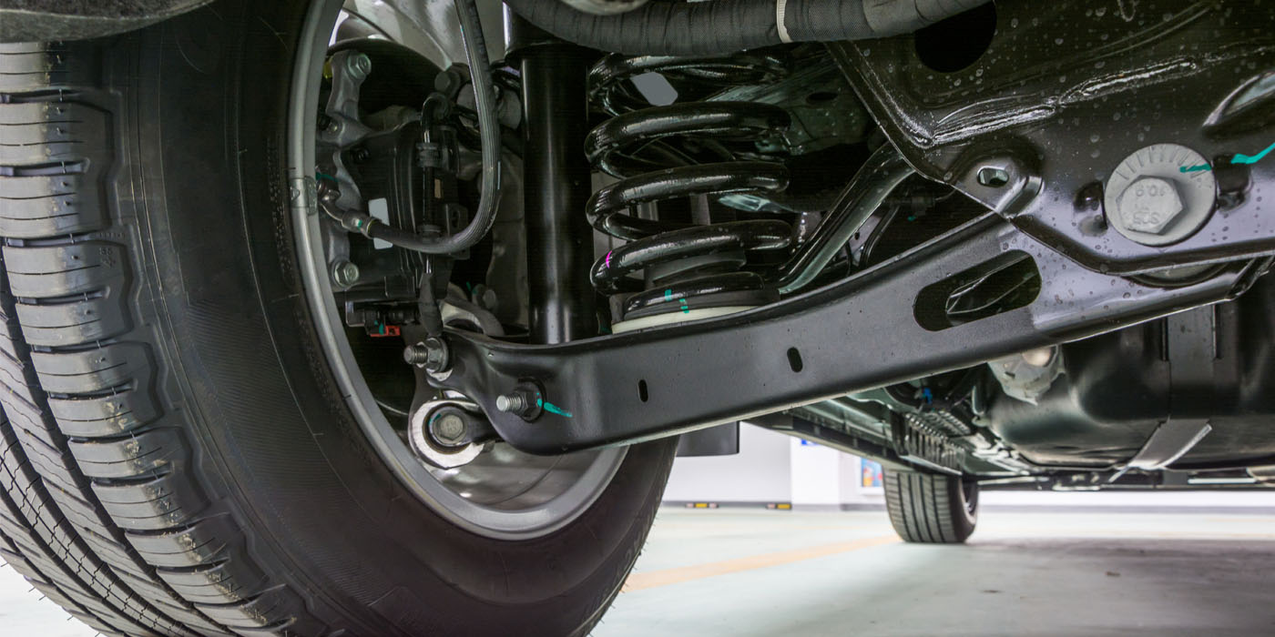
2. McPhearson Strut – When unitized vehicles entered the U.S. market, so did McPhearson Strut suspension. These systems reduced weight by eliminating the heavier two control arms and simplified the system since the spindle and shock absorber were designed together as a unit, rather than as separate pieces.
This system uses the inner fender aprons as the top mount for the assembly and, in the front suspension, the top pivoting point for turning. The lower arm may be designed as an A-Frame, Wishbone or, in many cases, a straighter arm single-mounted with a support bar/rod attached – sometimes called a radius rod. This rod provides forward and rearward movement support.
This system was introduced not only for weight savings, but also because it adapted more easily to front wheel drive. Since in a front-wheel-drive vehicle the engine is actually transverse (sideways), the drive axles must be able to enter the wheel spindle without having to avoid springs and shock absorbers. Even though a few vehicles in the past have used SLA and front-wheel-drive, the number is very small compared to McPhearson Strut designs, unless the suspension is modified to relocate the spring and shock absorber.
3. Twin I-Beam – Until 1997, Ford pickup trucks utilized a suspension that spanned multiple decades. The uniqueness of this system was that it basically took a straight axle concept and split the system into two halves, allowing each side to act independently.
Although this system has since been replaced with SLA systems, you need an understanding of it since vehicles with this system are still on the road and may end up in your shop for repairs.
Although many variations of all three designs exist, all such variations derive from the basic three. In addition, electronic sensors and controls to affect ride, braking, handling and feel are also included. Mistakes here can be costly, so it’s important to consult manufacturer service manuals when working with these systems.
Repair or Replace?

Since suspension systems must be able to absorb road shock and handle the forces of braking, acceleration and turning, the question is often whether parts of this system should be repaired or replaced.
In other countries, it’s common to repair some of the parts. Two factors have made this acceptable: the availability of the part, and the lack of liability and concern regarding human safety.
You see, many suspension parts can be produced in a casting process rather than a stamping (forging) process. The casting process is normally used for spindles, tie rod ends, steering knuckles and the I-Beam for Ford trucks from 1985-’97. This casting-type process produces a very strong part. However, once bent, the part’s strength is compromised and must be replaced. Although over the years, Ford I-Beams have been routinely “bent” to perform a wheel alignment, this was never a proper option. In fact, cast I-beams were clearly embossed directly on them to not weld or bend.
But it’s not just cast suspension parts that shouldn’t be repaired. Other suspension parts that aren’t cast also aren’t candidates for repair.
What you need to recognize here is the stress that these parts take on a regular basis. If we repair them and they’ve been weakened, we’ve compromised the safety of the people in that vehicle. And we are accountable.
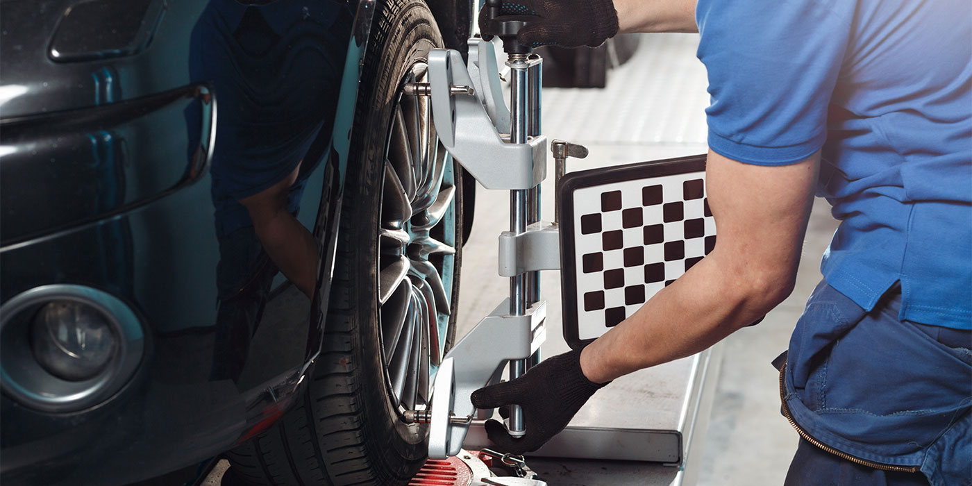
It’s All In the Angles
Diagnostic angles are integral to today’s collision structural repair and wheel alignment.
Let’s take a look at three of them:
1. Steering Axis Inclination (SAI) – SAI is defined as the inward tilt of the upper pivot point compared to the lower pivot point referenced to true vertical when viewed from the front or back. This is the angle created by a line drawn from point A through C and compared to true vertical. It’s the primary directional control angle for today’s vehicles. It’s measured in degrees, and there’s no positive or negative because the angle must lean in toward the center of the vehicle.
It’s critical to look at the SAI readings for every collision-related alignment. SAI is the key factor in validating proper structural dimensions in these suspension mounting areas during collision-related wheel alignments.
Unfortunately, most alignment technicians who perform retail alignments for consumers don’t know how to run these angles properly. Each current wheel-alignment system today has a very set procedure to perform these measurements. They’re not automatic, but they are clearly explained in the operation manual or help screens of today’s alignment systems. Still, many never properly perform this check. Why?
The main reason is that since typical retail outlets such as Firestone, Goodyear, etc., perform up to thousands more standard retail alignments each year than collision-related alignments, they don’t get into the habit of checking these important diagnostic angles. In fact, they may never have to. This is where they “assume” everything is correct. In a collision wheel alignment, however, if they assume this, they may attempt to fix a symptom rather than the real problem.
2. Camber – Camber is defined as the inward or outward tilt of the wheel at the top viewed from the front or back. This angle in most front and rear wheels needs to be checked and corrected within specification. It may or may not be adjustable, and it’s generally measured in degrees or fractions of degrees.
For example, if a line is drawn through the center line of the tire, that line represents the camber angle compared to true vertical. If the tire is leaning out at the top (viewed from the front or back), it’s called “positive camber.” If it’s leaning in at the top, then it’s called “negative camber.”
Engineers determine what the camber angle should be at rest (static) to change during driving (dynamic) to maximize vehicle control and handling. Ideally, having all the tire’s surface on the road (0 degrees camber) during driving would be an ideal goal. This would minimize tire wear and vehicle pulling. But getting the camber angle to stay at zero during all dynamic conditions is almost impossible since camber changes as the vehicle’s height from the road surface changes. This height change is due to slight changes in the road, acceleration and braking. But the more often it does stay at zero, the better for vehicle handling and the tires.
It’s also very important that side to side (left to right) comparisons of the camber angles are balanced or within specifications given by manufacturers. Generally, the collision repair industry should ensure that this balance is within 1/4 of a degree side to side and that each reading is on the same side of zero (both negative or both positive). This is referred to as the “split” or “cross camber.” Imbalance of camber readings and/or out-of-specification settings can easily cause the vehicle to pull to the side of most positive (front wheels and opposite for rear wheels).
3. Included Angle (IA) – IA is a calculated angle created by adding the SAI to the camber angle. IA determines if there are bent or misadjusted parts between the upper and lower pivot points of the suspension.
McPhearson Strut Systems and SAI
If structural repairs are com-pleted properly, the SAI on McPhearson Strut systems will be correct unless a lower control arm is bent, a ball joint stud is bent, the engine cradle has shifted side to side or the upper strut tower is mislocated.
If the technician, using even a tape or tram gauge, verifies the relative lower ball joint position from side to side and makes sure that the ball joint isn’t bent on either side and that the upper strut tower dimensions are the same left and right, then it’s reasonable to assume the SAI readings will be the same left and right. On a symmetrical vehicle, this also means that the structural dimensions for the lower and upper front structural relative to centerline are most likely correct.
This is definitely the time to find out that a possible alignment problem exists relative to the structural repairs – not once the job has been completed, painted and sent down to the alignment shop.
But what do you do if and when the alignment guy tells that you it won’t align? The questions to ask first are, “What are the SAI readings for both sides, and what are the camber readings for both sides?”
With or without specifications (many times SAI specifications aren’t published), this information can allow for a very quick diagnosis of the real problem.
If SAI angles are the same left and right, don’t go thinking that the frame is still bent. It isn’t. The problem is most likely a bent spindle or strut.
Now if the readings aren’t the same, it is remotely possible that the vehicle is non-symmetrical as well. Verify this through your structural dimension guides. This is a very remote possibility for only very few vehicles, but just make sure before you jump to conclusions.
The box below is a general guide to assist you in diagnosing the problem if SAI angles aren’t the same for left and right sides. Some great training programs are also available to train you and your staff on this diagnostic method. It’s well worth your time and money to understand this diagnosis system since it’s possible that your “alignment guy” doesn’t.
If SAI is lower than specification, look for damage low. If SAI is greater than specification, look for damage high. Also, in both cases, check that the lower ball joint isn’t bent. Left unchecked, this can misdirect many technicians into thinking damages exist in other areas. To check this, raise the wheels off the ground and manually grab the tire and move each wheel through its turning radius. Pay close attention to any abnormal (not smooth) rotation of the lower ball joint. This can be verified by removing the spindle from the ball joint and rotating the ball joint stud with vice grips attached. If it’s not bent, the stud will rotate centered and not wobble during turning.
You also need to look carefully at whether one side is less than specification and the other is greater than specification. In these cases, look first at the engine cradle or crossmember to ensure it’s properly positioned. These opposite-type readings usually indicate that it’s not. Once this has been corrected, re-check the SAI angles.
If no specifications for SAI are given, begin by assuming that the undamaged side (or least damaged) SAI reading provided is correct and use it as a guide for the other side. This can, however, be misleading so use caution before jumping to conclusions. Once you’ve verified the correct reading, write it down for the next time.
Don’t Rely Only on Camber Readings
In this area during a collision repair, there’s a tendency to replace anything that might be damaged, rather than finding what’s really causing the problem. This is usually caused when only the camber reading is used to diagnose the problem.
Keep in mind, improper camber angle readings are only a symptom of the real problem. It’s unfortunate the camber is what most alignment technicians “fix” at all costs, even if it dramatically affects other alignment angles. One of my main truths that I attempt to convey to any technician is, “No one should ever sacrifice one alignment angle to fix another. It must be properly diagnosed. Don’t react to only the symptom. Fix the real problem.”
For example, one reason camber readings may be out of specification is because the SAI angles are incorrect. And this would be the real problem, as opposed to the symptom – the camber being incorrect.
Another reason camber will be out of specification is because the IA is out of spec. As already noted, this calculated angle determines if there are bent or misadjusted parts between the upper and lower pivot points of the suspension. So, if the IA and camber are out of spec, then it’s likely that the strut and/or spindle is bent. (If there’s an adjustment for camber, check that first.)
As for special kits to “fix” camber problems, they should never be used to mask a problem with SAI or to mask a bent part, just as strut benders should never be used. Wheel alignment is the fine-tuning of wheels for optimum driving. Our proper diagnosis of the problem and performing proper structural repairs are crucial. The special kits diminish the importance of this and offer options that aren’t recommended or possibly aren’t safe.
Find and Fix the Problem
Even though we concentrated here on McPhearson Strut systems, you need to use the same diagnostic approach for all systems. Regardless of the suspension type, diagnostic angles are the key.
Are you getting accurate readings for these angles every time during a collision-related wheel alignment? If not, you’re assuming that they’re correct. My dentist can assume the angles are correct. So can the kid with pink hair and a pierced eyebrow who’s taking orders at the McDonald’s drive-through. But you, on the other hand, shouldn’t be assuming. You’ve got expertise and experience. Use them to diagnose and fix the problem.
Contributing Editor Tony Passwater is president of AEII, a consulting, training and system-development company. He’s been in the industry for more than 27 years; has been a collision repair facility owner, vocational educator and I-CAR international Instructor; and has taught seminars across North America, Korea and China. He can be contacted at (317) 290-0611, ext. 101, or at [email protected]. Visit his Web site at www.aeii.net for more information.