 For over 15 years, I was a weld quality examiner for I-CAR in Washington State. For all 15 of those years, it was steel that was welded, but then I-CAR introduced the Aluminum Weld Quality Test. I administered the preparation program, the test and the weld examination as well – a two-day process at that time.
Over that period of time, I looked at and inspected thousands of welds that technicians made during their tests. The initial Steel Weld Quality Test and the examination process were developed with I-CAR by the American Welding Society (AWS). It was the first hands-on test developed for the collision repair industry, and its purpose was to verify a collision repair technician’s ability to properly and safely weld a collision-damaged vehicle according to the manufacturer’s recommended procedures. This is important because, with the advent of the unibody vehicle, collision energy factors were being carefully engineered into the vehicle to allow the safest possible deformation of the vehicle structure to offer the maximum protection to the occupants.
When General Motors produced the Z06 Corvette with an aluminum frame, it mandated that any dealer wishing to sell the Z06 Corvette had to have at least one employee take and pass the I-CAR Aluminum Weld Quality Test – evidence that the OEs and insurers also were recognizing how critical weld quality is to the proper and safe repair of a collision-damaged vehicle.
Steel unibody cars have continued to employ more and stronger steels. Cheap gas has dried up, and so has the thirst for big, heavy SUVs. The lighter the vehicle, the more fuel efficient it is. Lighter cars mean lighter steels, which means the strength of the steel has to increase while the thickness has to be reduced. But there’s a problem with this scenario: the stronger these advanced high strength steels become, the more sensitive to heat they are. Certain welds can reduce their strength by as much as 50 percent.
With these advanced materials being used in vehicle construction to reduce weight gain and maintain the manufacturers’ construction methods for unibody and space frame type vehicles, it becomes vital that proper collision assembly methods be used to safely repair collision-damaged automobiles.
Reason to Worry
Over the span of my 15 years of examining thousands of welds, I experienced only about a 38 percent pass rate! That means that 62 percent of the students failed and needed to take the test again.
Our test locations didn’t employ a prep class for the steel test, but all students were given study materials, including videos that explained how to prepare for the test.
The test administrator would often ask the students if they had been practicing. A common reply was, “I don’t need to practice, I do this every day.” Problem is, they’re doing it on customers’ cars! If they’re failing on nice, clean metal with optimum conditions, it chills me to wonder what the heck is happening on the vehicles they’re working on every day.
Looks Are Deceiving
When I-CAR first came out with the Steel Weld Quality Test 18 years ago, I signed up for it. I paid my bread and was sent my prep materials, study guide and video. I reviewed the prep materials and set up at work as recommended to practice and destructively test the practice welds. These are done the same as the welds you’ll do during the actual test. The study material clearly describes the entire process.
I performed good-looking welds in the fillet, plug and butt weld with backing configurations (the subsequent tests have increased to include an open butt weld without backing and an additional weld test including actual sectioning procedures) in both a vertical position (not horizontal) and overhead position – a total of six welds at that time.
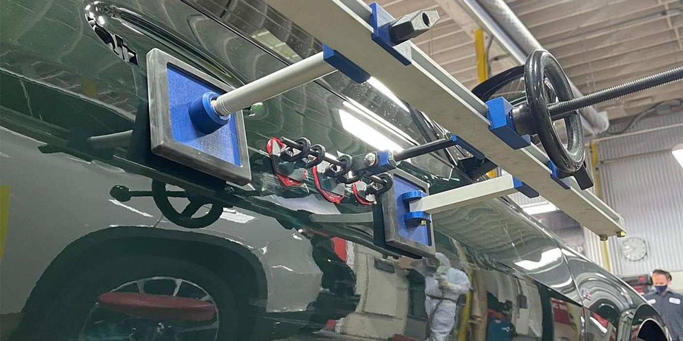
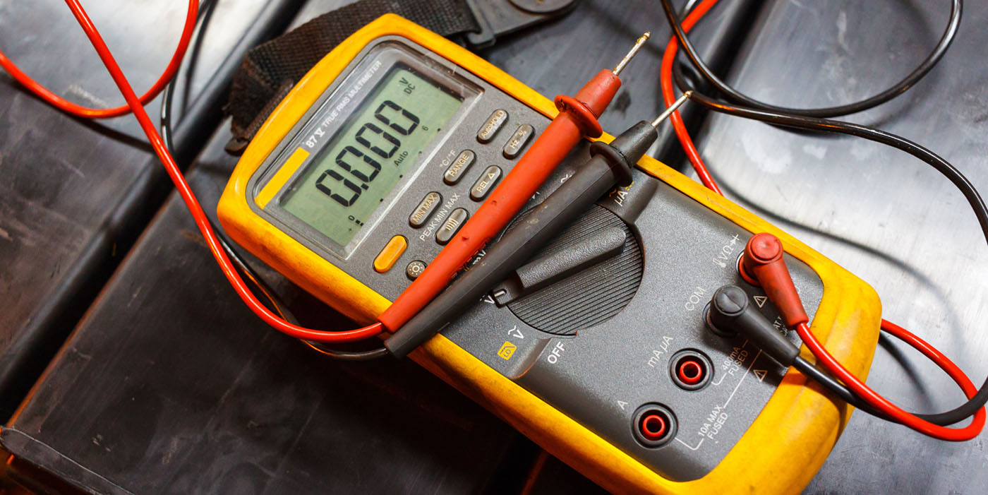
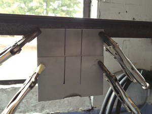
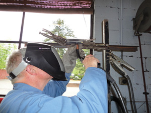
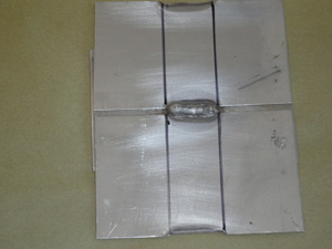
I checked my welds visually with the supplied checking gauge (Photo 1). Everything looked fine…no gaps, holes were filled, no burn-through and all welds measured properly with the gauge.
Then, I began to destructively test the welds, following the supplied instructions. Fillet weld, fine…proper tear-out in the overhead and vertical position. Plug welds…uh-oh, failure in the vertical position, not enough tear-out. That weld had looked just fine to me, too! The overhead plug was fine; I got more penetration in the overhead position than I did in the vertical.
Next, I destructively tested the butt weld with backing. This requires effort with a vice, chisel and heavy hammer. Again, the vertical weld failed. Dang! I never would’ve guessed it. It looked fine, and that’s my point here: Looks are deceiving!
The worst and most dangerous welds are the ones that look good or even beautiful but have no penetration and are destined to fail. A good-looking weld is not a sign of a strong weld.
Oh, I can hear the “nattering nabobs of negativism” right now, and they’re saying something like, “I’ll put my welds up against anybody’s.” Okay, okay, so you can lay down a beautiful weld. I’ll concede that, but until it’s destructively tested, you don’t know for sure if it’ll hold or not. You need to check it destructively just before making the same weld on a customer’s car. Believe me, this is crucial.
Following Instructions
Many of those thousands of welds I tested looked just fine. They passed the visual parameters of the test: correct length, not too short or too long. Why is that important, you ask? Because it speaks to the ability of a technician to read, understand and follow instructions.
The fillet weld and the butt welds have length requirements. If you’re not within the prescribed requirements of the test, you’ll fail the visual test. You could have the strongest, most beautiful welds out there, but if they’re not within the length requirements, you’ve just failed the test. That’s why practice is required.
Let me ask you this: If the requirements call for a weld with weld penetration tear-out of between 1 to 1-½ inches, why would anybody produce a weld that was 15/16 or perhaps 1- 9/16 inches long? These lengths are not the required lengths of the I-CAR Weld Quality Test. I saw hundreds of tests that fell in this category of failure.
Collision repairers are used to doing things their own way, moreso than mechanics who are used to following precise instructions in the recommended assembly sequence with exact torque tightening. So doing a procedure in an exact way is somewhat out of character for many collision techs…not all, but in my observation, about 62 percent. The strange thing was that on the second test, the pass rate went from 38 percent to 90 percent. This told me that if it’s going to cost somebody extra money to take a second test, that somebody isn’t going to be very happy.
Fear as a Motivator
So, properly inspired, the vast majority of technicians can pass the test. I saw this policy play out in another way, too. When the technicians in a specific shop would all take the weld quality test at once, they would either all have a 38 percent pass rate or they would all pass! My guess was that when the shop owner or manager realized how much money it cost to take the test, they took a personal interest in seeing how the practice was going, asking for visual results of passing welds long before anyone actually took the test. I know that I did the same, personally working with my techs to make sure they understood how to practice and destructively test those practice welds.
I knew most of those shops owners and managers whose techs had the high pass rates. They’re the ones who are actively involved with their people. They’re also the ones who fully understand the liability issues involved in what we do and do as much as they can to produce a safe, quality, liability-free repair and protect their customers’ investments and well-being. They’re professionals.
Where Can I Test?
Maybe the I-CAR Weld Quality Test isn’t available to you. It could be, though, considering it’s mobile and can come to you if it’s in your area.
But what should you do if you’re out of range? You should at the very least set up and test yourself and your techs to ensure that you’re producing high quality, safe, strong welds before you perform more structural welding. Frame rails, core supports, floor pans, rocker panels, A, B, C and D pillars, crossmembers and sills all require test welds prior to the actual welding on a customer’s car.
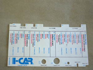
I can’t show you the exact requirements of the I-CAR Weld Quality Test because that would kind of be like cheating, but I will show you how to properly test your welds and what a passing grade looks like. You supply the practice welds and physical effort.
Coupons
For the purposes of this discussion, we’ll use three basic and common welds used in the shop: fillet weld, plug weld and butt weld with backing.
Let’s start with the metal we’re going to weld. It needs to be similar to the structural steel used in unibody vehicles. This is generally 18 gauge with a light zinc coating on it (galvaneel or galvanized). You can go to a steel supplier and buy it, or you can cut some steel from scrap you save from cars you’ve worked on. You should be cutting some pieces from the damaged part you’re replacing and performing a series of welds that you’ll use in the installation of the new structural part anyway. We’ll call these pieces “coupons.”
I gathered the coupons in the photos in this article from welds performed in the I-CAR Weld Quality Test. They were welded by students and then destructively tested by me and saved for practice purposes. They’re 3 inches by 5 inches and have light galvaneel coating to simulate the structural steel used in automobiles. You should make them all that size because it’s an easy test size to work with.
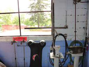
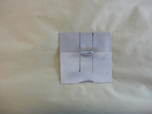
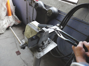
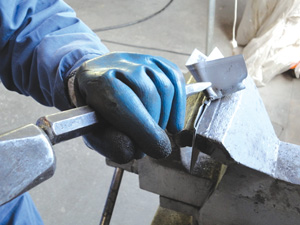
You’ll also need a couple of pieces of angle iron to make a holding fixture on which to clamp the coupons to when welding. I used some 1-½ inch by 1-½ inch by 1/8 inch pieces and clamped them in a vice so that I could use my vice grips and clamp the coupons to the angle, which is held by the vice (Photo 2).
Clean Your Coupons
Clean your coupons so they’re free of paint, undercoating or other pollutants to the weld. Do a good job of this because the quality of the weld depends on it. Porosity in a weld (air pockets) is caused by a dirty weld site, among other things. Take the guesswork out of it. If it’s predictable, it’s preventable. Your goal is to get a good weld the first time, not go through two dozen coupons as if you’re trying to create a photo display of every possible weld defect.
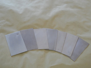
When the coupons are free of pollutants on the surface, wipe with wax and grease remover and dry with a clean towel (Photo 3).
Fillet Weld
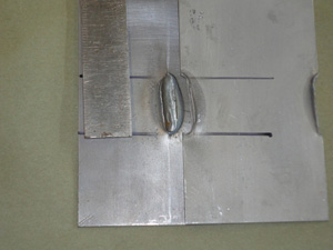
This weld doesn’t need further preparation because all you need to do is clamp two coupons together, with the top coupon overlapping the bottom coupon in the middle (Photo 4).
The weld length should be between 1 and 1-½ inches with full tear-out between those lengths. In other words, a minimum of 1 inch and a maximum of 1-½ inches; anything under or over that should be considered a failure. Come on, you say? Hey, that’s a whole ½-inch ballpark you’ve got to play in!
Mark off a distance of 1-¼ inches and use a black marker so that you can see it. Start and stop where the black marks are. Set up your welder just like you would in real life and perform the weld (Photo 5).
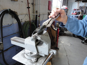
Destroy the Weld
Clamp the bottom coupon in a vice with the weld and the top coupon just above the vice jaws. Clamp your flat tong vice grips on the upper coupon and break the coupon off the weld (Photo 6). Inspect the top coupon for evidence of weld tear-out. The weld should remain on the bottom coupon and the top coupon should have a tear-out minimum of 1 inch and maximum of 1-½ inches (Photo 7). This weld passed the requirements, but if yours doesn’t…adjust your machine accordingly.
Overhead
Set up your coupon same way and mark it as you did in the vertical weld, only now you’re going to weld overhead as we sometimes have to under an automobile (Photo 8).
Destructively test this weld as you did the vertical fillet weld. If your weld fails, adjust your machine and technique until you complete a passing weld. Document your machine settings so that when you perform that weld in that position on the car you’re working on, you can set the welder accordingly.
Plug Weld
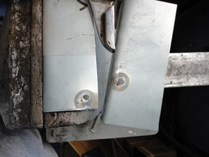
This weld will require an 8mm or a 5/16-inch hole punched in the top coupon. Weld through this hole in the top coupon into the bottom coupon and then twist off the top coupon, leaving the weld in the top coupon and tearing a hole in the bottom of a minimum of 3/16 inches or 5mm. If the hole is smaller than 3/16 inches or 5mm, or the weld spins off from the top coupon and stays on the bottom with no hole except the top coupon, it’s a failure (Photo 9). Perform this weld in both the vertical and overhead positions and destructively test it (Photo 10).
Butt Weld with Backing
This is a common weld for struct- ural repairs and it’s important that it be performed correctly in that it’s a common joint for sectioning a frame rail, pillar or rocker panel.
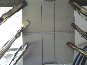
Setting up this weld takes three coupons: two top coupons and one bottom coupon. The gap between the two top coupons is crucial. If it’s too tight, you won’t realize enough penetration to achieve tear-out in the bottom coupon. If it’s too wide, the upper coupons will fall off during the destructive process with little penetration into the top coupons. Some have said the gap should be 2 to 4 coupon thicknesses. Allow enough to achieve good penetration into the bottom coupon (Photo 11).
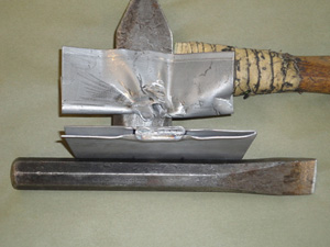
Mark and make the weld. Fold the two upper coupons together (back to back). Clamping the bottom coupon in the vice, fold the bottom coupon into a “U” shape using a 3-lb. hammer. Remove the bottom coupon from the vice and clamp the two top coupons tightly (Photo 12).
With a large chisel and heavy hammer, drive the U-shaped backing up, tearing metal out of the backing and leaving it on the weld on the two top coupons (Photo 13). You should tear out at least 1 inch of metal from the backing (Photo 14). Do not put the chisel directly in the joint; instead, use the chisel against the outer end of the U-shaped backing, causing the metal to tear at the weld site. This is the correct way to test this weld…but it requires physical strength, accuracy with a chisel and hammer, and endurance.
If you do this prior to making structural welds, you can be assured that you’ve done your best to make sure your welds hold in a collision – after a repair you’ve made.
To improve your welds, I suggest taking both I-CAR courses WCS03 and SPS05. May all your welds be strong.
Writer Mike West, a contributing editor to BodyShop Business, has been a shop owner for more than 30 years and a technician for more than 40 years. His shop in Seattle, Wash., has attained the I-CAR Gold Class distinction and the ASE Blue Seal of Excellence.