 A sometimes overlooked area after a vehicle is involved in an accident is the electrical wiring and components. It’s important that we as collision technicians diagnose problems with these components and fix them safely and properly.
More Electrical
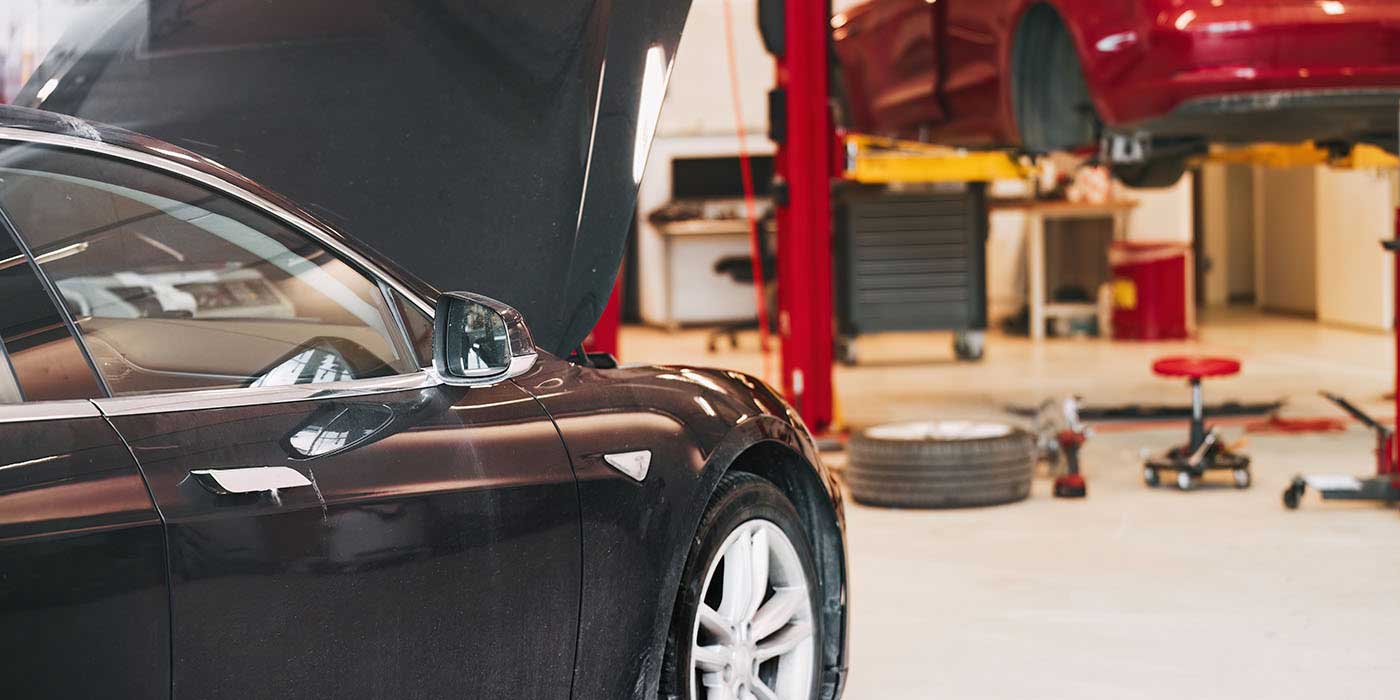
Today’s modern vehicles have more electrical and electronic components than vehicles of a decade ago, so there’s a greater chance of the wiring or electrical parts being damaged when the vehicle is involved in an accident. In a frontal impact, for example, wires that run through the radiator support can be severed, which can render the component they run to useless.
Consider also that most modern vehicles have the fuse boxes located under the hood near one of the front fenders, making them a target for collision damage. If a component (headlights, horn, taillights, etc.) doesn’t work after a wreck, you must take steps to troubleshoot and repair the problem.
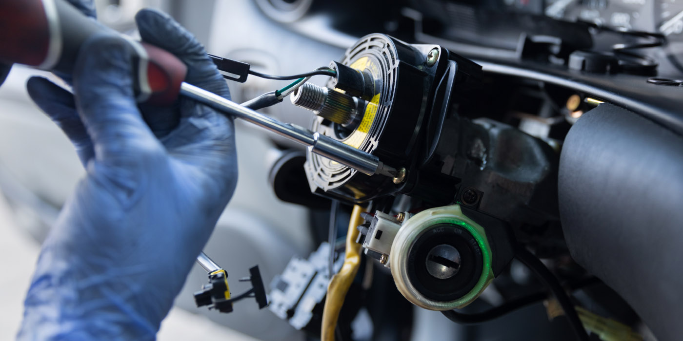
Physical Inspection
Always start your electrical investigation by physically looking at a suspected problem area. In some cases, a wiring connector could be pulled apart and would only need to be plugged back together. This would be an easy fix. However, there could be an electrical problem with the previously mentioned severed wire running through the radiator support. That’s much more difficult to diagnose.
Safety First
Automotive electrical safety is of the utmost importance. After you’ve completed your troubleshooting diagnosis, and before you’ve started on any electrical repairs, the battery should be disconnected on a gasoline 12-volt vehicle. This eliminates any further component damage like a short circuit, which could cause a fire.
Although you’ve disconnected the power source on a gasoline 12-volt system, you’re not out of the woods yet. Onboard computers such as the Powertrain Control Module (PCM), Engine Control Module (ECM) and even the vehicle radio need power to maintain their respective memory settings. This can be accomplished by means of a memory saver device, which keeps the power directed to these devices so the memory settings aren’t lost and costs fewer than $10 at an auto supply store. After attaching a 9-volt battery to one end, the other end goes into the vehicle’s auxiliary power outlet or, if equipped, the cigarette lighter outlet.
Hybrid Care
Hybrid and electric-type cars require other safety precautions. These motors and batteries generate much higher voltage than 12-volt systems.
According to General Motors, the large storage batteries on both their hybrid and electric vehicles are direct current rather than alternating current, which can carry a higher concentration of high voltage. These batteries range anywhere from 115 to 343 volts. The high-voltage cables are usually colored orange so that technicians as well as rescue workers (if the vehicle is in an accident) can steer clear of them.
When servicing either a hybrid or electric vehicle, always refer to the vehicle manual before starting any work. Safety glasses and heavy rubber electrician’s gloves (rated for 1,000 volts or more) should be worn when making these types of repairs.
Terminology
There are many terms you need to know when dealing with basic electricity:
Current. Current is the movement of electricity or electrons through a circuit or wire. This is measured in amps with an amp meter. The symbol for current is “A” or “I.”
Voltage. Voltage is the pressure that pushes the electricity through the circuit or wire. It’s measured in volts using a voltmeter. The symbol for voltage is “E” or “V.”
Resistance. Resistance is an obstacle or restriction to the current flow. It tries to stop the current caused by the applied voltage. Current or part resistance is measured in ohms using an ohmmeter. The symbol for resistance is “R” or “Ω.”
Conductor. A conductor carries current to the parts of a circuit.
Hot wires. Hot wires connect the battery positive to the components of each circuit.
Insulation. Insulation stops the current flow and keeps the current in the metal wire conductor. The steel body of the vehicle provides the ground conductor back to the negative battery cable.
Load. Load is the part of the circuit that converts electrical energy into another form of energy (heat, light, etc.)
Series circuit. Series circuit has only one conductor path or leg for current through a circuit. Current has to flow through components and wires one after the other. If any part of the circuit is opened (disconnected), the entire series circuit stops working.
Parallel circuit. A parallel circuit has two or more paths for current. The current can flow through either path independently. One path can be closed (electrically connected) and the other opened, and the closed path will still operate.
Series-parallel circuit. A series-parallel circuit is when a parallel circuit has both series and parallel branches in it. It has characteristics of both types of circuits. All the circuits in a vehicle can be classified and tested using the rules of these three (series, parallel and series-parallel) circuit types.
Ohm’s Law
“Ohm’s Law” is a mathematical formula for calculating an unknown electrical value (volts, ohms or amps) when two of the values are known. If you know two values, you can mathematically calculate the third unknown value:
Voltage = Current x Resistance
Current = Voltage ÷ Resistance
Resistance = Voltage ÷ Current
For example, if you know that a circuit has 12.6 volts and 2 amps, what’s the circuit resistance? Plug in your two known values into Ohm’s Law and you’ll find out that 12.6 ÷ 2 = 6.3 amps.
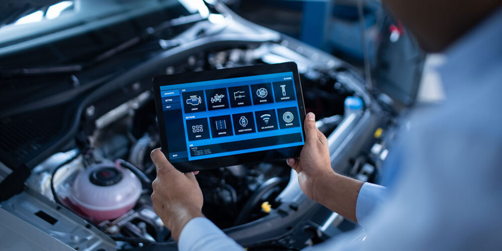
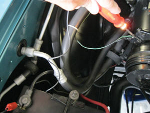
Testing Electrical Circuits
There are at least two test tools that can be used when checking circuits and wiring. The least expensive is a simple 12-volt test light that consists of a sharp probe connected to a small, 12-volt light bulb and ground wire with an alligator clip. You touch the probe to a positive-charged electrical component such as an air conditioner clutch wire and the other to (in this case) the negative battery post. If the light is on, this means there’s power to that circuit.
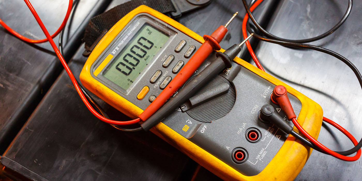
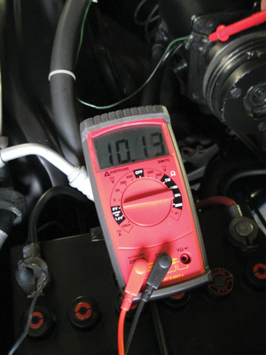
The second diagnostic tool is a digital multi-meter, which can be purchased at a home improvement store for under $30. It has many more uses than the 12-volt test light. It’s very accurate and measures voltage to within a hundredth of a volt.
The automobile manufacturers recommend this type of multi-meter because it will not damage delicate electronic components. A high-impedance (10 mega-ohm input) is recommended to avoid damage to these voltage-sensitive components. Digital multi-meters are to be used in conjunction with the vehicle’s service manual.
Checking for Continuity
A circuit remains closed and operational when it has continuity. Sometimes the vehicle service manual will ask for a continuity check of a wire or component. The continuity check is done to see if the electrical circuit has a complete path without any opens, which would stop the flow. Here are the steps:
1. Set the range selector switch on the highest resistance range position.
2. Connect the multi-meter test leads to the opposite ends of the wire or component being tested.
3. Read the meter. An infinite reading (maximum resistance) shows an open circuit. A zero reading shows continuity.
Measuring Voltage
The multi-meter allows you to select both alternating current voltage (ACV) and direct current voltage (DCV).
ACV is selected when measuring alternating current. Alternating current is found in hybrid and electric cars and can be identified by orange wires and connectors. It can also be found in common house wiring.
DCV is selected when measuring direct current voltage. DC is the type of current found in modern vehicles. Some signals from sensors, however, can be AC.
Measuring Current
Current or amperage is some-times measured to check the consumption of power by a load. For example, current draw is often measured when checking the condition of a starter motor.
Modern ammeters have an inductive pickup that slips over the wire or cable to measure current. A high current draw indicates a low resistance. An example would be a dragging or partially shorted motor. A low current draw means there’s a high resistance in the circuit, perhaps from a bad connection or dirty motor brushes.
Checking for Shorts
Many times during a collision, adjoining wires within a harness get pinched together or severed. A multi-meter check will detect a severed wire. When checking for a short between two adjoining wires in a harness:
1. Set the multi-meter range selector switch as you would for a continuity check.
2. Connect the multi-meter test leads to the opposite ends of the adjoining wires.
3. Because the wires are insulated, there should be a reading of almost infinity on the meter. If the multi-meter reads zero, the wires are shorted to ground or another ground wire.
Wiring Diagrams
To troubleshoot electrical problems, it’s often necessary to use an electrical wiring diagram, which can be found either in the manufacturer’s or an aftermarket service manual.
Abbreviations are used on wiring diagrams so that more information can be given. The service manual will have a chart explaining each abbreviation, number and symbol on the diagram.
Most wires on the diagram will be identified by their insulation color. This color-coding allows you to find a specific wire in a harness or connector. The color code abbreviation chart can be found at the front of the wiring diagram section of the service manual. Different auto manufacturers use different color coding abbreviations on their wiring diagrams.
A wiring diagram is more like a book than a picture. You can’t understand a wiring diagram just by glancing at it. Like a book, you must read the diagram carefully all the way through for a complete understanding.
Electrical Components
Switch. A switch is used to turn a circuit off or on by hand. When a switch is closed (on), the circuit is connected.
Relay. A relay is a remote control switch. The relay coil acts upon the movable arm to close the relay contacts. This allows the small switch to control high current going to the load. A relay is commonly used with electric motors since they draw a heavy current. A bad relay will usually have burnt contacts or points that prevent the flow to the component.
Motors. Motors use permanent magnets and electromagnets to convert electrical energy into a rotation motion for doing work. Faulty motors could have worn bushings or brushes that can decrease overall efficiency. They might also have winding shorts and opens that prevent motor operation.
Circuit breakers. Circuit breakers heat up and open with excess current to protect the circuit. They do not suffer internal damage like a fuse. Many circuits are protected by circuit breakers. They can be mounted on top of a fuse panel or in-line. Like fuses, they’re rated in amperes.
Fuses. Fuses burn in half with excessive current. They’re normally placed between the power source and the rest of the circuit. Modern vehicles use either the blade or spade-type fuse.
Fusible links. Fusible links are small-diameter wire spliced into the larger circuit wiring for over-current protection. These devices are usually found in the engine compartment near the battery. They’re often installed in the positive battery lead that powers the ignition switch and circuits that are live with the key off.
Conclusion
Many technicians will tell you that electrical problems are the most difficult to solve. But as long as you have an understanding of basic electricity, these tasks will become easier and take less time as you become accustomed to these procedures.
John D. Lyman, Sr. has been the collision repair instructor at the Forbes Road Career & Technology Center in Monroeville, Pa., since 1991. He has worked in the collision repair industry since 1974, is ASE- and PPG-certified and holds a Master’s degree in education. He can be reached at [email protected].