Cylindrical glass tubes with metal end caps vs. plastic mini fuses. Large mechanical switches vs. IC circuits. Throttle cables vs. drive-by-wire. Distributors vs. coil-on-plug ignition systems. Noisy steering shafts vs. steer-by-wire. No matter how much vehicles change, you can always count on them breaking and someone having to learn how to
repair them.
Over the past 30 years, electrical systems have changed so much that many of today’s technicians don’t understand yesterday’s systems any better than many of my generation understand today’s systems. The simple fact is that we learn what we’re exposed to the most. When you’ve had problems and gone through all the sweat and torture it takes to figure out all of the ins and outs of a system and its intricacies, you never forget that experience. Sure, there are many of you out there who can tell me how to set up everything from a magneto all the way up to today’s drive-by-wire systems, but you’re the ones who’ve been dealing with these systems for many years on a daily basis.
When I started working in this industry, the general consensus was that wiring problems were a nightmare. It’s funny, then, that no matter how many things have changed, this still remains the case today.
First off, I don’t want you to think I’m the “all-knowing expert” on electrical problems. I only wish that were true! The reality is that I’ve been tripped up many times by electrical scenarios that should’ve been simple to fix. I’ve had to seek experts to help me so many times that they’ve come to dread seeing me come their way. I’m just like all of you: a collision repair technician who, because of the nature of his work, has to have a basic understanding of all of a vehicle’s systems.
Unfortunately, electrical systems are some of the hardest to understand. I’m hoping to help you avoid some growing pains by discussing a few things that have amazed me in the past as well as a few things I’ve learned to watch out for.
Fix It Right, Dimbulb
I’ve seen ground problems throw many technicians for a loop. For example, a test lamp illuminates yet the component still won’t work because the tech neglected to consider that the ground could be severed or compromised. Remember, as simple as this sounds, you need both B+ and B– to make a circuit complete. Some techs tell me that the B– is zero and the B+ is 12, giving you a voltage drop across the battery of 12 volts. That makes sense, but remember, this is one of those cases where zero is very different from nothing. As a matter of fact, it can be everything that’s wrong with your circuit when it fails.
Many of you have probably experienced what I call the “Combs Syndrome,” which is occasionally found in a vehicle that has been involved in a collision. I call it the “Combs Syndrome” because the bulbs just don’t seem as bright as they should be (har-de-har-har). The problem is usually a ground that’s cut loose, yet the bulbs illuminate dimly. When troubleshooting this problem, techs are inclined to think that the ground must be good or else the lamp wouldn’t illuminate at all. But if they have a schematic and checked the ground distribution, they’d see where the lamp circuit in question was most likely spliced with another lamp circuit. Once the ground is severed below the ground splice, the circuit will try to ground itself using the element from an adjoining bulb circuit it’s connected to through the splice, effectively turning a parallel circuit into a series circuit. In this instance, the voltage is split between the other lamps in the newly changed circuit, giving us the dimly lit bulb effect.
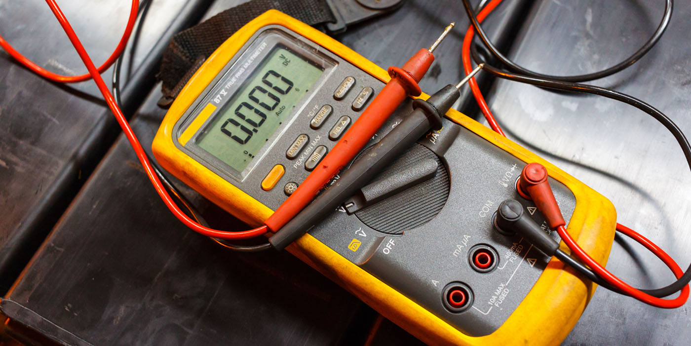
If we were to use a voltmeter to check this circuit, we could find the problem by checking for voltage drop between the bulb socket ground terminal and a known-good ground with the circuit live. Of course, we could also find the problem by using an ohmmeter to check for high resistance with the circuit dead. Voltage drop should be very low here. Zero is perfect, but you can see variances because even wiring has some resistance, which is what causes voltage drop. You can probably relate this to the drop you get in air pressure at the end of an air hose. When resistance, whether it be from a length of wire or air hose, goes up, voltage, or pressure, goes down. That goes back to one of Newton’s laws, which states, “For every action, there is an equal and opposite reaction.”
Study the Schematic
Talking about resistance reminds me of a story one of our General Motors trainers named John told me one day. John is one of the few trainers I’ve dealt with who has actually worked on the line for many years as a tech. Let’s just say he knows where we’re coming from. He’s also more knowledgeable about automobiles than any instructor or technician I know. It’s funny how hard knocks can be the best teacher. As an example, John was in a session with some electrical engineers and trainers discussing some of the circuits on a high-end GM vehicle when he noticed a misprint. When he pointed out that the schematic showed that the ground for the headlamp was mistakenly shown in the car’s rear area, one of the engineers, with a shake of his head, indicated that it was no misprint, explaining that the electrical system on this vehicle had so much load potential that they had to “juice” the alternator.
OK, so we now have more voltage potential when the vehicle is at max charge. The voltage threshold that the headlamp can stand is near the same voltage the alternator puts out. To protect against overpowering the headlamp circuit, an exceptionally long ground sub-circuit is built into the headlamp circuit to provide adequate resistance and keep from blowing the high-dollar HID lamps in the circuit when the alternator is at max charge state. When I heard this, I immediately panicked, thinking back on repairs I’d made in the past that involved ground circuits that were compromised. Sometimes, the wiring on these vehicles was not overly friendly to access. If I had a bad ground and was having trouble tracing the wire down to find the fault, there was a good chance that I would just make a “new” ground for that circuit. After all, all you need is positive voltage (which I had) and negative voltage (which was available on most metal surfaces), right? Well, in the past that would work, but now…just think of the possibilities. If I’d have made the same “new ground” on the headlamp system mentioned in the story above, all of a sudden I’d have started smoking expensive HID headlamps. I might have said, “All I get is junk parts any more. None of these bulbs last!” But how long would it have taken me to realize what the problem was? Three bulbs? Four? I would have been scratching my head a long time before I figured that one out. I might have even said, “I couldn’t have caused it because all I did was repair the ground.”
The lesson here is that when doing repairs, particularly when you’re troubleshooting a problem child, sometimes an extended look at the schematic for unusual things can give you a clue as to what may be wrong.
Know Your Circuit
I’m sure most of you have
reluctantly been introduced to the many digital circuits found in vehicles today, which allow these vehicles to do amazing things electronically compared with cars of yesteryear. I’ve noticed that the wires keep getting smaller and smaller and control more and more things. And you have to do different things to check digital signals from what you had to do with the old “do you have power” circuits. At the training center, they tell us you can use a voltmeter to check these circuits. Before you get too involved with the voltmeter, though, you need to familiarize yourself with the circuit you’re working on.
In the service manual, you have two tools to do just that: a “Description and Operation” section that offers an overview of how a particular circuit operates and what happens when it’s operated, and also “Schematic and Wiring Diagrams.”
Once you’re familiar with how a circuit works, you have to activate it by pressing a button or whatever triggers the particular one you’re working on. Once the circuit is activated, you should see “something” on the voltmeter, which simply means you should see a variation of voltage. If you don’t see any activity on the line, that circuit has no “conversation” going on, so to speak. But if you see “something” as far as voltage changing, that circuit is having a conversation and it, in all likelihood, is good. These circuits are typically talking to a computer of some sort, and that computer decides, from the conversation it receives, which device or devices need to be turned on.
In the old circuits I cut my teeth on, the positive side was usually the side that was switched, and those circuits were usually hardwired to the ground. Most of today’s digital circuits are now switching the negative side of a circuit to activate the component involved, which causes less arcing in the circuit, giving less wear. But like so many things in the past, these digital circuits are still just about moving electrons to make something happen.
Take Your Medicine
I know that grounds aren’t the only things we have problems with electrically, and I know the thoughts in this article are pretty short and maybe not so sweet. But this, like anything we try to learn, is like taking bad-tasting medicine: If we mix it in slow with all of the other things we’re taking in, it becomes part of us and we most likely won’t even taste it. When we face anything we’re unfamiliar with, our first reaction may be to “sublet.” But if we learn the unfamiliar, we’re adding the opportunity to line our own pockets and provide a better repair experience for the customer. Whatever the reason for all of the changes we have to deal with, one thing’s for sure: We had better learn to work on them and live with them or we could end up just like a circuit without a ground!
|
8 Troubleshooting Tips
|
Contributing Editor Keith Combs is the body shop manager at Bill Roberts Chevrolet, where he’s been employed for more than 25 years. He was named GM/ASE Master Collision Repair/Refinish Technician of the year in 2000 and was one of the first to achieve GM’s World Class Technician status in 2002.