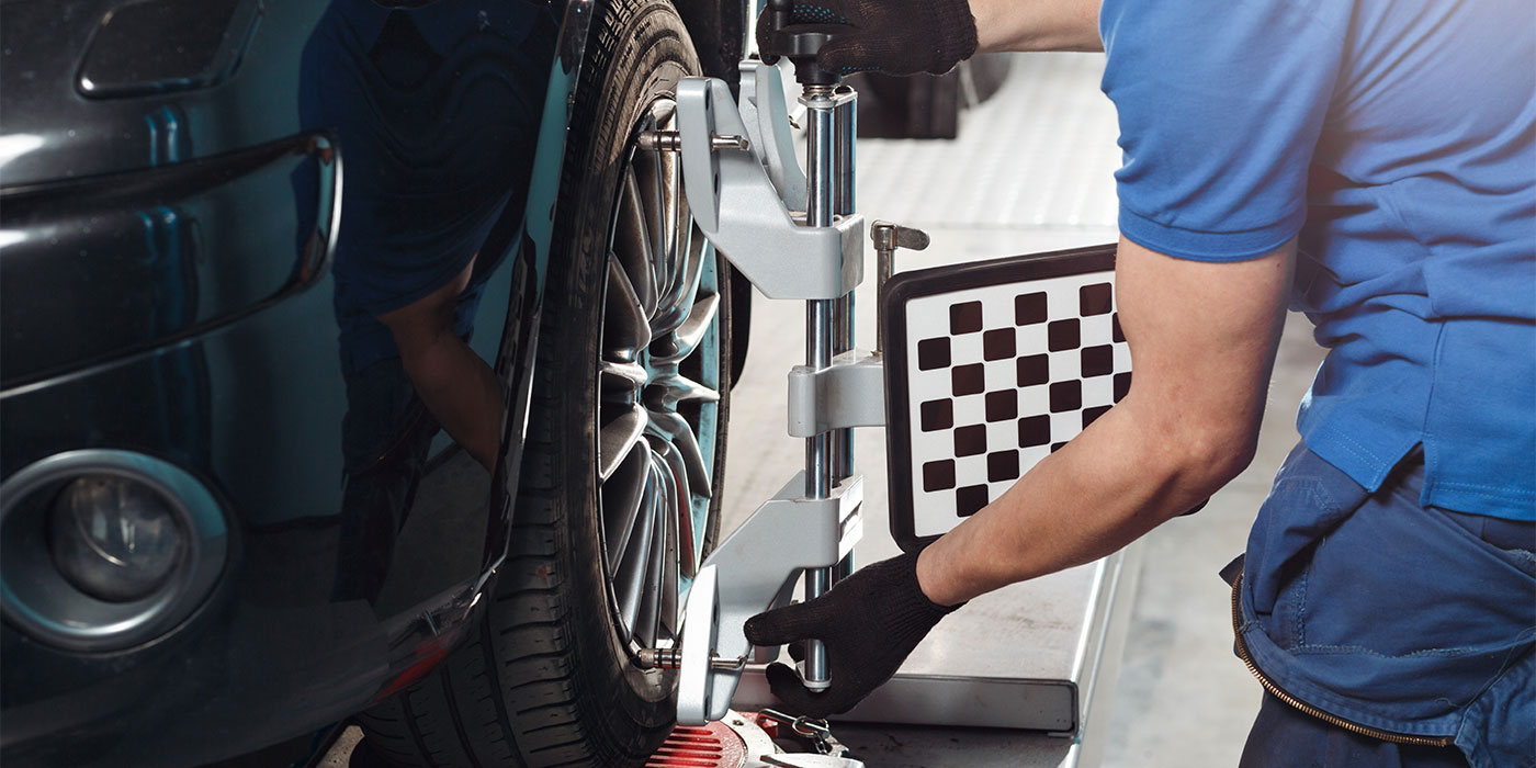
As collision repair techs, we need to accumulate a wide variety of skills and training to do our jobs – and one area in which techs tend to stumble is wheel alignment. Since most shops either subcontract wheel alignments to a specialist or keep a trained mechanic on duty, many techs are still somewhat overwhelmed when they look over a spec sheet. And when the alignment tech tells us the front wheels can’t be returned to OEM specs, we’re not always quite sure what to look for to correct the problem.
With a better understanding of the alignment process and the angles involved, you can often pinpoint suspension damage before sending the vehicle to the alignment tech.
Understanding the Basics
Before looking for damage, make sure you have a basic understanding of a few alignment terms. Five basic front-end geometric angles are common to all vehicles and perform two basic functions: position the steering axis, which controls directional stability and handling; position the wheels so that tires can maintain maximum road contact with minimum tire wear.
The five angles are steering axis inclination (SAI), caster, camber, turning radius and toe. Caster and SAI position the steering axis of each wheel.
Steering Axis Inclination (SAI)
SAI is an imaginary line running through the upper and lower ball joints (pivot joints) on short- and long-arm suspensions. On strut suspensions, the steering axis passes through the lower ball joints and the upper end of the strut. SAI is the angle of the inward tilt of the steering axis and is measured in degrees from true vertical.
SAI provides good driving and handling characteristics through directional stability and weight projection. Directional stability is the tendency of a wheel to straighten from a turned position and remain straight. As the wheel is turned, the spindle swings on a downward arc, and the weight of the vehicle forces the spindle to return to the highest point in the arc, returning the wheel to a straight-ahead position. Weight projection is the projection of a vehicle’s weight to a point within the road contact area of the tire. The weight projection point at the road surface is the point where the wheel pivots for turning.
A true plumb line, placed at the center of the wheel at the point of road contact, and the projected line created by the strut or the upper and lower ball joints determine SAI. The two lines will intersect at a point just below the road surface on most vehicles, but on some front-wheel drive vehicles, the point of intersection will be just above the road surface.
The distance between the projected line and the vertical line at the road surface is called scrub radius. Scrub radius is positive when the projected line is inward of the true vertical line at the road surface and the point of intersection is below the road surface.
Positive scrub radius forces the front wheels to toe-out when the vehicle is in motion. This is usually found on rear-wheel-drive vehicles.
Negative scrub radius places the projected line outward of the true vertical line, and the point of intersection is above the road surface. This forces the front wheels to toe-in to provide stability when braking on front-wheel-drive vehicles.
SAI is a directional-control angle. The point of intersection is designed by manufacturers to provide a pivot point for the front wheels when cornering. SAI isn’t adjustable on most vehicles and is usually only affected by loose, worn or damaged suspension parts or by frame damage.
Caster
Caster is the position of the steering axis from true vertical when viewed from the side. The steering axis and a true vertical line passing through the spindle form the caster angle.
The purpose of caster angle is to provide directional-control stability for the front wheels to travel a straight course with minimal effort. Proper caster angle also helps to return the front wheels to a straight-ahead position after a turn. Caster is adjustable on most short/long-arm suspensions on passenger cars and light-duty trucks to compensate for normal wear in suspension and steering.
Positive caster is the backward tilt of the steering knuckle at the top. This places the vehicle point-of-load ahead of the point-of-contact at the road surface, which provides good directional control.
Negative caster is the forward tilt of the steering knuckle at the top. This places the point-of-contact ahead of the point-of-load, which provides easier steering at slower speeds. Negative caster doesn’t provide good directional-control stability. The vehicle must instead rely on its SAI angle and wide tires for directional control. Caster is a directional-control angle and can be used to offset road crown on most short/long-arm suspensions.
Unequal caster causes the vehicle to pull to the side with the least positive caster.
Too much positive caster out of factory specs causes hard steering and excessive road shock and shimmy.
Too much negative caster causes instability at high speeds.
When caster is out of factory specs, the vehicle should be checked for loose, worn or damaged suspension and steering parts before alignment. Frame damage also affects caster angle.
Camber
Camber is the inward or outward tilt of the wheel at the top, measured in degrees from true vertical. Proper camber angle provides directional-control stability by placing maximum tire tread in contact with the road surface under all driving conditions. Camber is adjustable on most domestic cars and light trucks.
Positive camber is an outward tilt of the wheel.
Negative camber is an inward tilt of the wheel.
Unequal camber causes the vehicle to pull toward the side with the most positive (outward) camber.
Camber can be used to offset road crown on most short/long-arm suspensions. Improper camber settings can cause uneven tire wear and wheel bearing wear.
Included Angle
Included angle (IA) is the sum of the camber and SAI angles and should be within 1/2 degree from side to side. On a unibody vehicle, the two angles that tell the most about the condition of the suspension are SAI and IA.
If SAI is off, either the vehicle structure or a suspension mounting part is bent of out of proper specs. If the IA is off, there’s a bent or damaged suspension part. SAI and IA should be within tolerance before any other alignment adjustments are made.
Turning Radius
Turning radius angle is the angle formed by the amount the front wheels toe-out on turns. The purpose of turning radius is to steer the vehicle through turns with minimum tire wear. It’s a non-adjustable angle built in by the manufacturer and is the angle you should check any time you have an excessive toe reading or if there’s body/frame damage to the front of the vehicle. This prevents covering up bent parts with a toe adjustment.
The amount of turning radius for each vehicle is established by the wheel base and tire width. Turning radius is controlled by the angle of the steering arms to the center line of the wheel. Each steering arm has its own arc of travel as the front wheels are turned. Turning causes the inside wheel to turn more sharply than the outside wheel, setting up a “toe-out on turns” effect. This toe-out effect aids in steering through turns with minimal tire wear. When turning, the inside wheel will always have the greater angle because the inside wheel must turn more sharply.
Turning radius will become a tire-wearing angle if it’s not within factory specs. Early indications of turning radius tire wear will appear as a featheredge tread or a scuff on the edge or side of the tire tread. Extended periods of turning-radius tire wear will appear smooth on the edge or side of the tire tread.
On any vehicle, when turning radius isn’t within factory specs, the technician should always check for a bent steering arm, bent tie rod or bent center drag link.
Since turning radius is a non-adjustable angle, the only way to correct a misalignment is to replace any bent parts or repair the damaged frame or body structure.
An excessive toe angle (up next) can also affect turning radius.
Toe Angle
Toe angle is the distance between the wheels when a measurement is taken at the front and rear of the wheels. The purpose of toe angle is to compensate for tolerances in steering linkage and the effect of positive/negative scrub radius when the vehicle travels down the road.
When the front of the wheels are closer together than the rear of the wheels, they have a toe-in angle.
When the front of the wheels are farther apart than the rear, they’re toed-out.
Toe-in is recorded as positive toe angle, and toe-out is negative. Toe measurement is the distance from the center line of the vehicle to the front of each wheel. Toe can be measured in inches, decimal degrees or millimeters.
Toe will become a tire-wearing angle if it isn’t kept within factory specifications. Early indication of toe tire wear is usually a featheredge or scuff on the edge of the tire tread surface. Toe tire wear can also be found on rear tires as a featheredge or smooth edge on the tire tread surface.
Toe angle is adjustable on the front wheels on all vehicles and is adjustable on the rear wheels of many vehicles. Toe is adjusted by turning the threaded sleeve or rod, which adjusts the length of the tie rod.
Worn or bent suspension parts or changes in caster/camber settings can cause variations from factory specs. Body structure or frame damage can also affect toe angle.
Looking for Damage
We’ve all had those front-end-damaged vehicles that seemed to drive around the parking lot OK and passed all the initial visual inspections and the bounce and rebound test, etc. But for some reason, something couldn’t seem to be adjusted to within specs on the alignment rack. And a very common practice is to throw parts at the problem until it goes away.
The best time to look for suspension and steering-component damage is while the vehicle is on the frame machine, with the full measuring system set up as well. Before any vehicle goes to the alignment shop, you need to know that you’ve returned the structure to factory specs. You also need to be especially sure that the strut towers are in their specified positions to ensure correct SAI angle, since SAI is non-adjustable.
If you know for sure that your frame/structure is returned to OEM specs and you’re confident that the SAI angle is correct, but the alignment tech has a problem, check the included angle (IA).
If IA is off, you most likely have a bent suspension part.
Many unibodies have lower control arms mounted on the front frame rails while others have the control arms mounted on a subframe or a crossmember that’s bolted to the unibody’s structure. Check the lower control arm mount bolts to ensure they’re within specification. Then measure from the front lower control arm bolt to the ball joint on the side of the vehicle that received most of the impact. Compare it to the same measurement on the other side.
If the lower control arm bolts are within factory specs but the ball joint measurement is shorter on one side, you probably have some damage to the lower control arm on that side.
It’s a good idea to check the lower control arm bolt measurements first because that will tell you if the cradle has shifted or if you’ve overlooked some damage. Cradle shift is among the most misdiagnosed conditions in accident-damaged vehicles.
Sometimes cradle damage or suspension damage is diagnosed as cradle shift, and sometimes cradle shift gets a thousand dollars worth of suspension parts and labor before it’s correctly diagnosed.
Generally, if the specs are off on one side, you probably have a bent part. But if specs are off on both sides, the cradle may have shifted upon impact in the accident.
You may be able to detect damage to a spindle by comparing right side to left side measurements to matching points on each spindle. While holding a straightedge against the rotor, measure the distance from the straightedge to the casting mark at the top of the spindle.
You can also check the distance to the steering knuckle the same way. I’ve found that two ordinary rulers are as handy as anything for this quick check for damage.
To check some struts, you can remove a cover at the top center of the strut to reveal the top end of the strut rod. Many strut rods can be turned with a hex wrench or a hex key or an Allen wrench (or whatever it’s called in your neck of the woods). Turn the strut rod with an air ratchet and watch the wheel while the rod is turning. If the top of the wheel moves in and out as the rod rotates, you know the rod is bent.
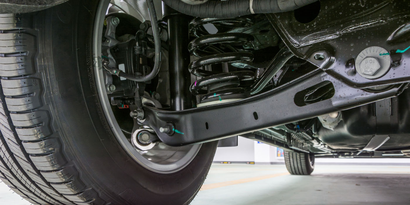
Last, but not least, let’s not forget the importance of the rear suspension and the role it plays in vehicle handling. Even on a front-hit wreck, inertial damage may alter the alignment of some rear suspension components.
Inspect control arm bushing or leaf spring bushings for wear or damage, since they help to keep the rear wheels properly aligned with the front wheels, which in turn keep the vehicle tracking properly. Damaged rear suspension parts or mounting points can lead to tracking problems and tire wear and may even cause some problems with the drive train, such as U-joint wear. Though the front wheels may be properly aligned, you may still have vehicle-handling problems and premature tire wear if the rear suspension is misaligned.
Quit Spinning Your Wheels
Wheel alignment doesn’t have to be a mystery. By learning the basic angles and gaining a better understanding of how they work together, you can more accurately diagnose damage and save time and aggravation in the long run for both you and the alignment tech. Most importantly, by properly diagnosing the damage early in the repair process, you’ll eliminate guessing games later.
Writer Paul Bailey, a contributing editor to BodyShop Business, has been a collision repairman for more than 20 years and is an avid photographer and writer who maintains a consumer-awareness Web page in his spare time. He resides in Florida with his wife, Cathy. Bailey can be reached by e-mail at [email protected].