There has been a lot of talk on new steels and their role in reducing vehicle weight. Reducing weight is not the only goal, though; increasing strength is a major component in their development. Now, let’s add longevity to the mix to make the vehicle last as long as it’s designed to and then some.
Making material to do this creates a need for recommended procedures to assemble and repair them. Steels today are constantly changing as far as alloys and mechanical properties. Not knowing how attachment procedures affect the new steels could expose a shop to disastrous liability. “I’ve been doing it this way for 20 years” is a phrase that just bristles the hairs on the back of the neck.
OEM Recommendations
It has never been more important to follow manufacturers’ recommendations, but the reasons may not always be obvious to us. Then again, we’re not engineers or metallurgists.
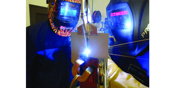
We’ve seen squeeze-type resistance spot welding (STRSW) being recommended more and more over the years, and new equipment has made that all possible in shops. When not possible, we’ve used GMAW (MIG/MAG) welding in the form of steel plug welds, but now car manufacturers are saying this is no longer recommended. Instead, they’re calling for MIG brazing.
HSS, AHSS, DP, HSLA and martensitic steels are all advancements in alloys and heat treatment processes. The heat created during steel welding may damage the mechanical properties of these steels, and it also can vaporize coatings such as zinc and create corrosion problems, negating the advantages of these steels.

Differences
MIG brazing has become one answer to the dilemma of too much heat. By using a low-heat adhesion process versus a high-heat fusion process, the heat is reduced and the corrosion and mechanical properties of these steels are retained. Steel welding creates temperatures of 3,000 degrees F, or 1,650 degrees C, to melt filler metal and fuse base metals. This fusion process can damage the molecular structure of the steel surrounding the weld zone, creating a weak spot that would change the dynamics or performance in a collision.
Zinc coatings also are affected by the high heat. Galvanized coatings can be vaporized from the repair area. This may not be an issue if a technician has access to the backside and can properly protect the weld zone. However, in areas where access is limited, this becomes a corrosion hot spot. The life of the repair could be shortened by the weld process used, affecting not just your shop’s reputation but also creating major liability.
MIG brazing generates heat of roughly 1,940 degrees F or 1,060 degrees C, melting only the copper/silicon wire filler material. This allows the metal to flow and bond to the surface of the metal. This flowing, similar to a sweating process, gives the weld a larger footprint or surface area contact than a steel fusion weld, offering a stronger bond without damaging the steel’s molecular structure. This low-heat process also allows for the galvanizing to remain near the weld zone and theoretically flow back into the area to protect the weld, leading to better longevity of the repair. This kind of repair can be duplicated in a repair shop, unlike laser brazing or other methods that are not available. Thus, shops can duplicate with confidence.
Copper/Silicon Wire Advantages
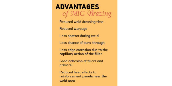
MIG brazing has other advantages too. The lower heat used to bond can reduce the time of dressing a weld, as the wire is softer. Warpage also is reduced by the controlled use of heat. Other advantages include:
- Les spatter during weld
- Less chance of burn-through
- Less edge corrosion due to the capillary action of the filler
- Good adhesion of fillers and primers
- Reduced heat effects to reinforcement panels near the
weld area.
The strength of copper/silicon wire also is an advantage. The ability to bond to the surface of steel without fusion is strong. The copper silicon wire has a tensile strength of 35,000 psi, whereas the average steel wire used in
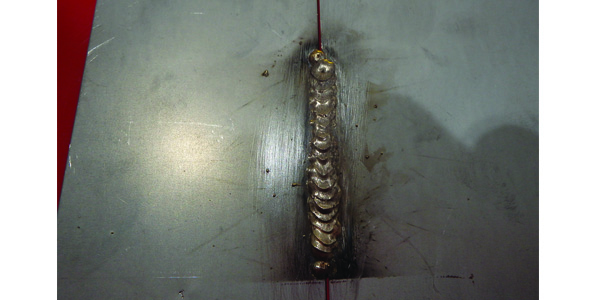
repairs is 70,000 psi. Although half the strength, when done correctly, the surface area of the weld offers a greater footprint and increases the strength compared to a low-surface-area fusion weld. The capillary action or flow of copper silicon spreads readily between surfaces of metal being joined. On an open butt joint, the capillary action forms a bead on the front and back of metal while bonding to the edges too. Unlike steel welding, the root gap is larger to accommodate the capillary action. This gives a large surface bond, creating strengths similar to fusion welds.
Where plug welds would be recommended, it may be a slot or two plug welds a certain distance apart. The welding pattern used creates heat and allows filler wire to flow between the metal in the heated area instead of just the edge of the hole. Following this pattern is critical for successful welds. This enlarged area again gives great strength comparable to fusion welding. A large amount of wire is used, so the diameter of the filler wire is usually large, 1.0 to 1.2 being common.
Equipment
Pay attention to differences in equipment if you want to make the business decision of using MIG brazing according to manufacturer certifications. Manufacturer certifications will require specific abilities or machines, so do your homework.
You must have a machine with power that can maintain an arc in a low-heat setting. A machine with 220 volts and a synergic or pulse setting is best, as it’s a spray arc versus a short-circuit process. You can choose to do manual settings, but the learning curve is higher as you can’t use traditional steel welding parameters. If you’re using older manual machines, a great deal of practice will be required. Getting settings correct and troubleshooting problems can often get in the way of proficient welding.
Although an added expense, most new welders have an automated setting needed for MIG brazing. Although automated practice will be key, I strongly suggest that practice be done on similar metals prior to welding. Differences in thickness and galvanizing can add a degree of difficulty.
As this is a MIG process, an inert gas is required, argon being the most commonly used. The shielding gas is important to control heat and minimize contamination during welding. The 100 percent argon also keeps the weld temperature lower, which is a goal of MIG brazing.
The torch liners must be made of Teflon or a similar material as the wire is soft and must easily move through it, limiting damage and particle throw-off. The rollers should be a half round. The decision on whether you use a toothed roller or not should be made by the welder manufacturer, as there are differing opinions on this subject.
Technique
MIG brazing is recommended as a push technique with a stitch or skip method. This has many advantages for the technician. First, when working with coated materials, the vaporized zinc must be allowed to escape the weld. Using a pulling technique traps the zinc into the weld, which causes excessive and unwanted porosity in the weld. Stitch versus continuous has heat control advantages. I’ve seen some good continuous welds lately, but these are on pulse machines that have dedicated settings.
A second advantage is sight. The lower current and voltage settings used for MIG brazing cause the arc to be smaller than what’s used in steel and aluminum. As with any weld, being able to see how the arc is reacting is necessary to succeed.
Along with better heat control, the push technique is recommended. However, some technicians have had success with a pull technique. It depends on the length of weld. Stitch welding could be done in this manner after a test braze and destructive test proves it works for the steel being brazed.
Settings should be for wire type and diameter, and these will factor in the metal thickness, zinc coatings and type of joint, as many automated settings are for a lap joint of two pieces of the same thickness. If a different joint or material thickness is used, this will change the settings. The welders aren’t wrong – it’s just that you’re doing a different brazing joint than the preset was set for. Once the setting is tested, brazing is ready. Saving this setting may not be beneficial, as the differences in zinc will affect the welds.
As the arc is smaller and harder to see, you should have a set of cheaters in the welding helmet, which gives a technician the ability to see the arc and reaction.
Metal
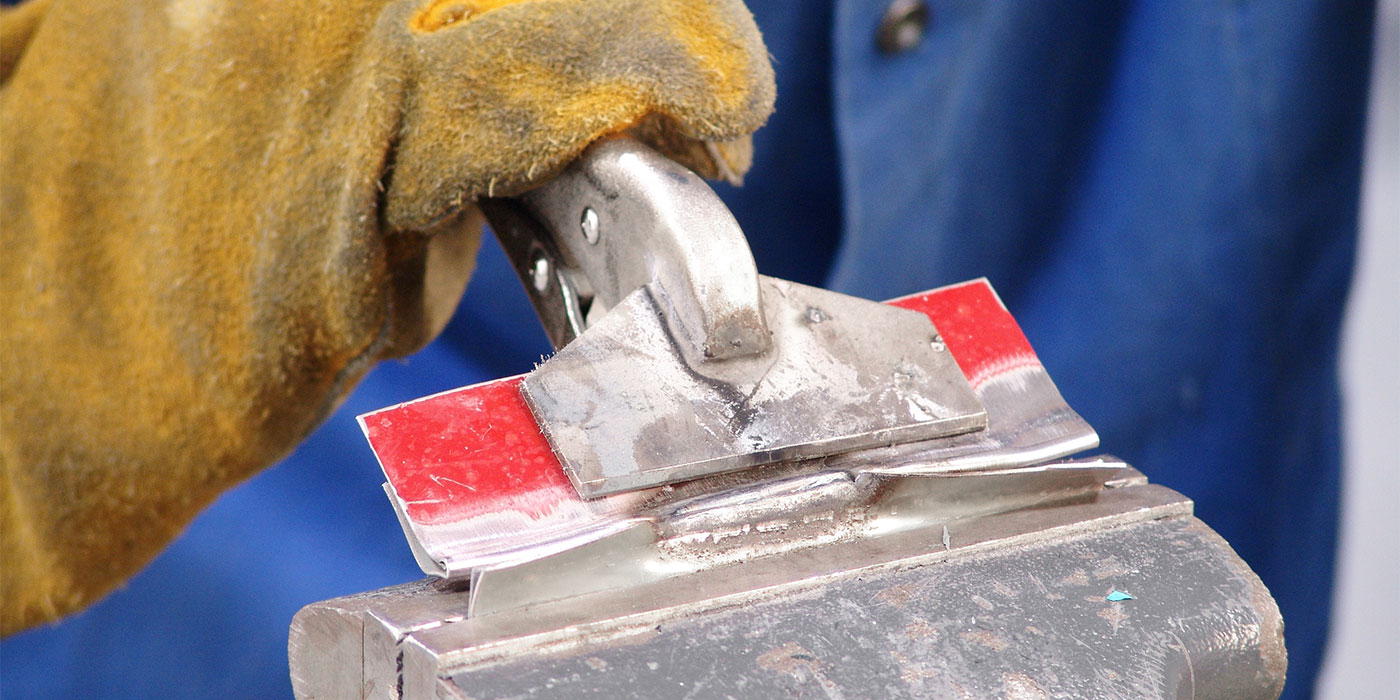
The fit-up of MIG brazing is different than steel. Instead of a plug, a slot may be required. The pattern for creating the heat to allow the flow of material must be followed, as this will give the footprint necessary for the braze to meet manufacturer requirements. When doing a root gap on a butt joint, follow manufacturer guidelines. The gaps will look huge in comparison, but the thickness of wire and low heat required will allow bridging of the gaps with no burn-through on the edges.
The bead may not flow out like steel. This is OK, as getting the bead flatter and flowing would require more heat, defeating the purpose of MIG brazing. The taller bead is acceptable and will be dressed down. This also limits the warpage of metal, requiring less body fillers.
Dressing Welds
You could leave them or if dressing is required, use 80 grit sand paper. The soft material will sand easily. Be careful not to go too far. If all the material is removed, the strength of the braze will be compromised. Normal priming and filler procedures will not be affected by filler metal.
Summary
As vehicle manufacturers keep changing the materials we work with, we as an industry must keep up with the changes. I recommend taking I-CAR courses on MIG brazing. Even companies not using I-CAR currently can take advantage of the programs. Along with aluminum welding and rivet bonding, all of these programs are excellent at preparing techs for cars currently using this process and more.