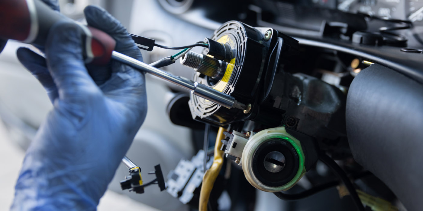
For stability control and steering sensors to be accurate, most of them need to be calibrated on the vehicle, either with a scan tool, specific procedures or a short period of driving.
Modern vehicles need to know the difference between what the driver “wants” and what the vehicle is actually “doing.” The vehicle uses sensors that measure steering angle, brake pedal position and throttle angle to know where the driver wants the vehicle to go. Other sensors measure what the vehicle is actually doing with wheel speed, yaw and acceleration sensors.
By comparing what the driver is asking to actual events, the stability control system can decide what the vehicle “should” be doing and make corrections.
For these stability control and steering sensors to be accurate, most of them need to be calibrated on the vehicle, either with a scan tool, specific procedures or a short period of driving. If a sensor can’t be calibrated, the customer could be back with a malfunction indicator light on after a procedure as complex as an alignment or as routine as a battery replacement.
Steering Angle
Measuring the steering wheel position angle, rate of turn and torque applied by the driver is typically the job of a sensor cluster that contains multiple steering angle sensors.
The sensor cluster will always have more than one steering angle sensor, and some sensor clusters have three sensors for redundancy or for improving the resolution of the sensor cluster and to confirm the data. It is important for the ABS/ESC module to receive two signals to verify the steering wheel’s position. These signals are often out of phase with each other.
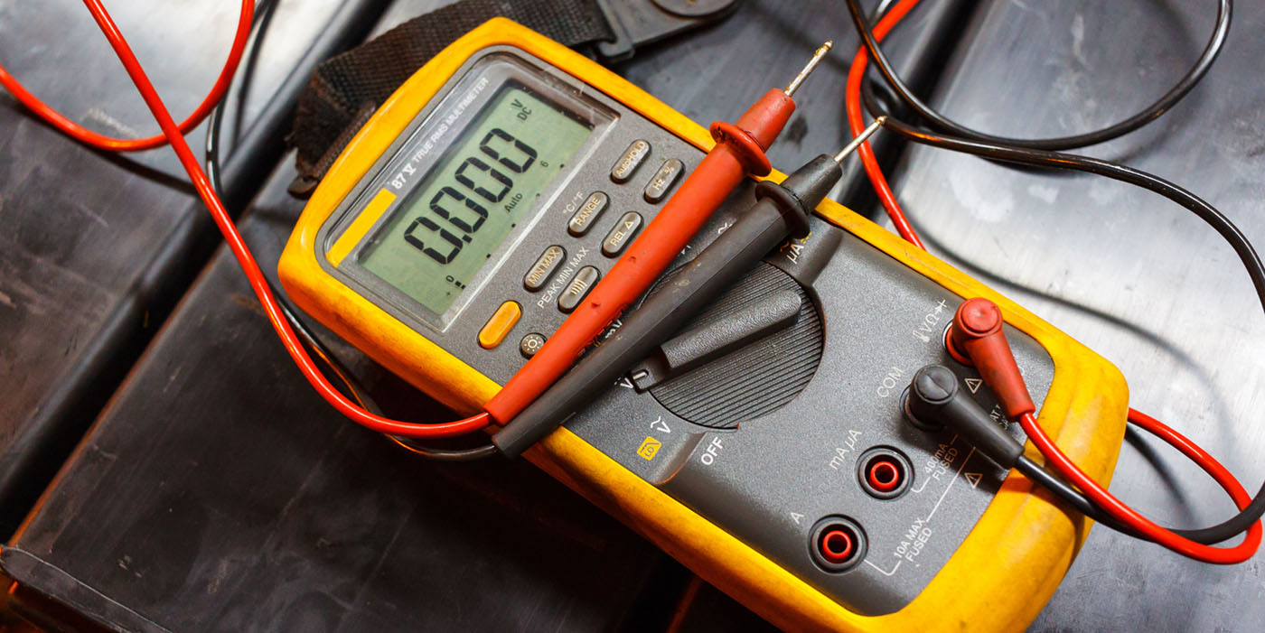
Analog SASs are similar to throttle position sensors. SASs are wired with a 5-volt reference, chassis ground and signal output. To test the SAS, you have to back probe a connector that is typically under the steering column.
As the steering wheel is turned, the SAS produces a signal that toggles between 0 and 5 volts as the wheel is turned 360º. As the wheel is turned lock-to-lock, the voltage will reach 5 volts three times and 0 volts three times.
On most vehicles, turning to the right creates a positive voltage and to the left generates a negative voltage. But, some systems are the opposite. The lab scope pattern shows the signal traces from the two sensors on top of each other. This can be helpful when comparing the signals and if one is
flat lining.
A digital SAS is often called a “contactless sensor.” This type of sensor uses an LED light, a wheel that acts as a shutter and an optical sensor that measures interruption in the light. The signal for these types of sensors is a digital square-wave signal. The frequency of the voltage changes depending on the speed the wheel
is turning.
The sensor clusters for these sensors often contain a third sensor to measure if the wheel is centered. With the wheel straight, the voltage is close to 0 volts. When the steering wheel is moved off center, the voltage goes high.
Some scan tools will display the data as an angle. In some cases, you can see the voltages from the sensors.
Torque Sensor
Measuring the amount of force being applied by the driver to the steering wheel is used by both the stability control and power steering systems. The information can be used to determine driver intentions and the performance of the power steering system. But, it can also detect a
steering pull.
The torque sensor performs the same function as the torsion bar and spool valve in a hydraulic system. The electronic sensor uses a torsion sensor in the same manner as in the spool valve in a hydraulic power steering system. There are different types of electronic torque sensors, and they are classified as contact and non-contact types.
The non-contact sensor uses a magnetic rotor with alternating pole pieces attached to the torsion bar. A sensor monitors the twist of the torsion bar by measuring the change in magnetic flux generated in the vanes located on the stator rings.
A contact-type sensor uses a wiper attached to the torsion bar and voltage divider attached to the rotating bridge circuit on the steering shaft to measure the twist of the torsion bar. The change in resistance is used to measure the torque applied to the steering shaft.
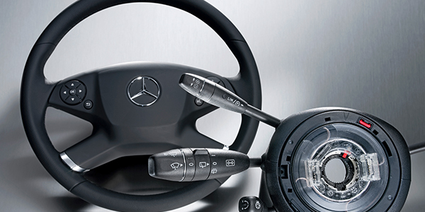
Steering Sensor Clusters
Most vehicles mount the steering angle and torque sensors in a single module on the steering shaft. Some call it a steering sensor cluster. The module connects to a Controller Area Network (CAN) bus. On some vehicles, it can connect directly to the ABS/ESC module.
A CAN bus is a high-speed serial data network that communicates in binary language to other modules or nodes. When you connect your scan tool to a vehicle, it becomes a node on a network. High-speed CAN buses use only two wires per module or node to communicate vast amounts of data. This means that a node, like a steering sensor cluster module, has to have the ability to interpret and create signals that can be understood by other modules on the bus. The best way to test modules on a high-speed CAN bus is with a scan tool. Most scan tools can look at the data directly.
On some vehicles, the SAS sensor cluster is part of a module that may include switches for the turn signals, steering wheel audio controls and wipers. Often, the torque and steering angle sensor can’t be replaced on their own. It might require replacement of the entire unit.
Resetting Sensors
Many vehicles require the SAS to be reset or recalibrated after an alignment is performed (even if the rear toe is adjusted) or components in the steering system are replaced. There are three types of reset procedures:
- First, systems that self-calibrate on their own.
- Second, vehicles that require specific wires to be grounded or buttons be pressed.
- Third, systems that require recalibration with a scan tool.
Even if the SAS is out of calibration, most vehicles have ways to sense if it is traveling in a straight line. If the angle is far enough out of range, it might set a trouble code and disable the ABS and/or ESC system.
Self-Calibration
On some import vehicles, recalibrating the sensor after an alignment or if the battery has died, is just a matter of turning the wheels lock to lock, centering the wheel and cycling the key. This “auto learn” functionality is becoming more common on newer vehicles.
Scan Tool Steering Angle Sensor Reset
There are many options for scan tools to reset steering angle and torque sensors. Some tools are even integrated into an alignment system. But, most tools recommend that the calibration be performed on a level surface. This is because you are also calibrating the yaw and accelerometers.
Also, it is always a good idea to perform a lock-to-lock steering wheel turn to complete the calibration.
This article was originally published in Import Car.