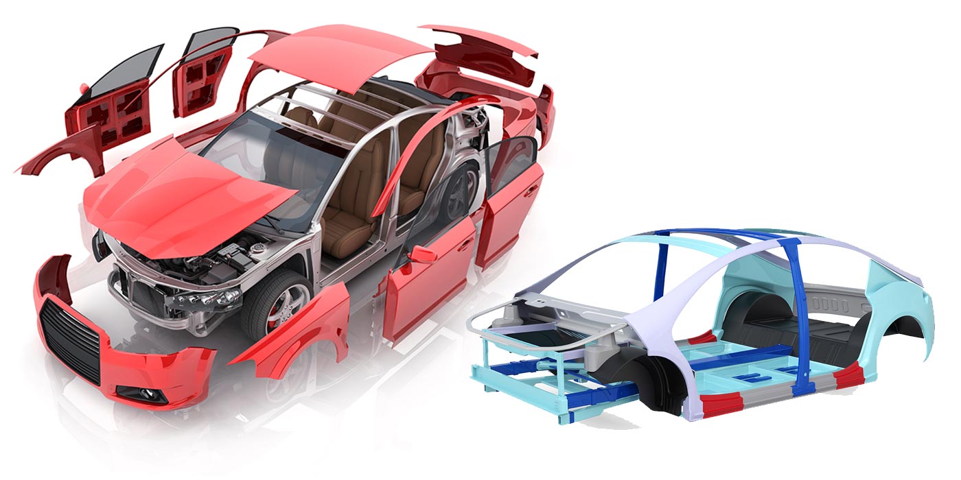
New vehicle designs and repair procedures are being developed by manufacturers every day. Keeping up with all the various replacement methods and techniques is a daunting task. The acceptable way of doing a correct repair yesterday may be out of date today.
This article describes such a repair procedure – sectioning a quarter panel on a 2005 Pontiac G6.
Description
This repair procedure gives you the option of using an installation procedure for either metal-inert gas (MIG) welding or adhesive bonding.
Service Procedure
Always refer to ALLDATA for safety procedures, identification of material types and refinish procedures.
Always refer to Pontiac for questions relating to applicable or non-applicable warranty repair information.
Step 1
• Disconnect the negative battery cable.
Step 2
• Disable the SIR system.
Step 3
• Restore as much of the damage as possible to the factory specifications.
Step 4
• Remove all related panels and components.
Step 5
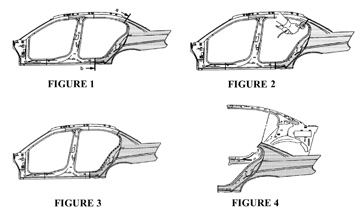
• Note the locations and remove the sealers and anti-corrosion materials from the repair area as necessary.
– Section the sail panel (a) and the rocker panel (b) (figure 1).
– At the sail panel, measure from the back glass opening down 120mm (4 3/4 in.) Scribe a line.
– At the rocker panel, measure 70mm (2 3/4 in.) rearward from
the rocker panel locating hole. Scribe a line.
Step 6
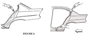
• Locate and drill out all factory welds. Note the number and location of welds for installation of the quarter panel (figure 2).
IMPORTANT: Do not damage any other panel or reinforcements when cutting at the marked locations.
Step 7
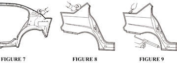
• Cut the panel at the marked locations (figure 3).
Step 8
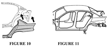
• Remove the lower quarter panel (figure 4).
Service Procedure
(MIG Welding)
Always refer to ALLDATA® for safety procedures, identification of material types and refinish procedures.
Always refer to Pontiac for questions relating to applicable or non-applicable warranty repair information.
IMPORTANT: To allow proper layout and cutting of the service part, review the sectioning information in the removal procedure.
Step 1
• Locate the area on the service part where the sectioning will be performed.
Step 2
• Measure and mark the cut line location on the service area.
Step 3
• Cut the service panel at the marked locations (a, b). Trim the sectioning butt joints to allow a gap equal to the metal thickness at the sectioning joint.
Step 4
• Create backing plates 50mm (2 in.) for the sail panel and 100mm (4 in.) for the rocker panel. Create backing plates from the unused portion of the service part.
Step 5
• Trim the backing plates as necessary to fit behind the panel at the sectioning joints.
Step 6
• Drill 8mm (5/16 in.) plug weld holes as necessary in locations noted from the original quarter panel.
IMPORTANT: If the location of the original plug weld holes can’t be determined, or if structural weld-through adhesive is present, space the plug weld holes every 40mm (1 1/2 in.) apart.
Step 7
• Prepare all mating surfaces as necessary. Apply 3M Weld-Thru coating part # 05916 or equivalent to all mating surfaces (figure 5).
Step 8
• Perform the sectioning procedure.
Step 9
• Plug weld accordingly.
Step 10
• Stitch-weld the sail panel and rocker panel accordingly (figure 6).
Step 11
• Clean and prepare all welded surfaces.
Step 12
• Apply the sealers and anti-corrosion materials to the repair area as necessary.
Step 13
• Paint the repair area.
Step 14
• Install all related panels and components.
Step 15
• Enable the SIR system.
Step 16
• Connect the negative battery cable.
Service Procedure (Adhesive Bonding)
Step 1
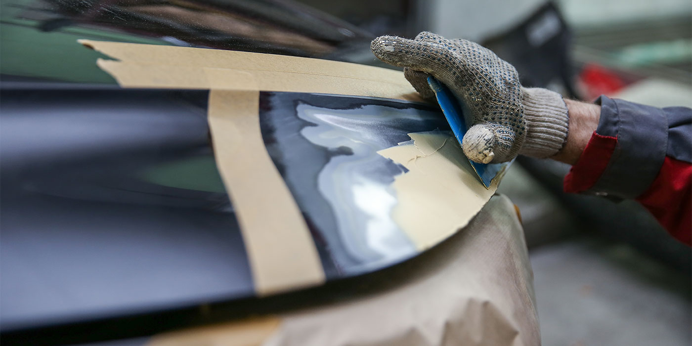
• Grind the surfaces of the mating flanges to bare steel (figure 7).
Step 2
• Grind the quarter panel mating flanges to remove the e-coating. Take care not to damage the corners or thin the metal during the grinding operation (figure 8).
Step 3
• Clean the mating surfaces.
Step 4
• Perform the sectioning procedure.
IMPORTANT: The adhesive has a 40 to 50 minute working time. Do not allow the adhesive to totally cure off the vehicle, as proper alignment of the lower quarter panel to the body will be difficult.
Step 5
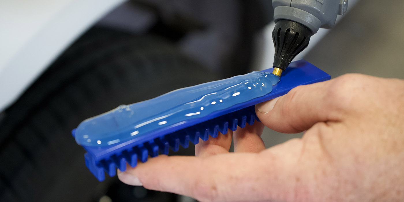
• Apply a 3- to 6-mm (1/8-1/4 in.) bead of metal bonding adhesive GM Part # 12378567 or equivalent to both of the mating surfaces.
Step 6
• Using a small acid brush, spread a coat of the adhesive to cover all the bare metal surfaces to ensure corrosion protection.
Step 7
• Apply a 9- to 13-mm (3/8 to 1/2 in.) bead of metal panel bonding adhesive GM part # 12378567 (Canadian Part # 88901675) or equivalent to the service part mating surface (figure 9).
IMPORTANT: Do not pull the panels apart after they’re joined together. Slide the panels against each other to realign the panels.
Step 8
• Install the quarter panel to the body (figure 10).
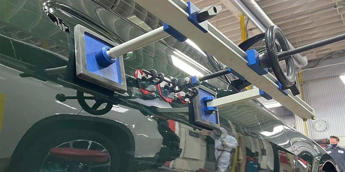
Step 9
• Clamp the quarter panel into position as required (figure 11).
Step 10
• Using lacquer thinner, remove the excess adhesive from the lower quarter panel area.
Step 11
• Apply the sealers and the anti-corrosion materials to the repair area as necessary.
Step 12
• Paint the repair area.
Step 13
• Install all related panels and components.
Step 14
• Enable the SIR system.
Step 15
• Connect the negative battery cable.
Writer Dan Espersen is the ALLDATA CollisionConnect Program Manager. Espersen is I-CAR Platinum Certified, a Gold Pin Member of the Collision Industry Conference (CIC) and holds an AA Degree in Automotive Technology. He has 15 years of experience in the collision industry and 17 years of experience in the automotive industry.
© 2007 ALLDATA LLC. All rights reserved. All technical information, images and specifications are from the
ALLDATA Product. ALLDATA is a registered trademark of ALLDATA LLC. All other marks are the property of their respective holders. Pontiac and G6, are registered trademarks of the Pontiac Motor Division and are being used solely for reference and application purposes. 3M is a registered trademark of Minnesota Mining and Manufacturing Corporation and is being used solely for reference and application purposes.