I was in a collision repair shop recently conducting an
I-CAR welding test where I was observing a tech installing a quarter panel using a squeeze-type resistance spot welding (STRSW) machine. I asked the technician how he knew if his welds were good. He looked at me as if I’d asked him a stupid question and said: “I know these are good welds because of the spark the weld makes.”
“The more sparks the better?” I asked.
His reply: “Yeah, man, let the sparks fly,” adding, “You should know that because you’re an I-CAR welding instructor. Let the sparks fly.”
I took a survey that night of the shop’s seven technicians, and they all agreed with the first tech — that sparks indicated that the plug welds were good.
During a break, I inspected the tips on the shop’s welder. First, the copper electrodes had been sharpened with a grinder but not with the grinder furnished with the machine. The ends of the tips were uneven and were about 11 mm in diameter. I pulled the trigger on the gun to check if the tips made full contact with each other and, sure enough, they didn’t. (I’ll explain these two points later in the article). I proceeded to pull the tips from the machine, and with a file, I dressed them. I then aligned the tips, and using some scrap steel (from a damaged door), I demonstrated to the techs how to make proper plugs. And guess what? NO SPARKS!
Yes, you read it correctly. There should be little or no spark when performing STRSW welds.
A lack of knowledge seems to surround STRSW. Another case in point: During a recent Collision Industry Conference (CIC) meeting, a shop owner complained that he had purchased a STRSW welder. After it arrived at his shop, he was informed that his facility needed to be rewired to accommodate the new welder. Exactly $7,000 later, he got his new welder functioning — and soon realized it wouldn’t reach a number of the areas on the front structure. After spending another couple grand, he finally had an operational welder.
What upset him the most about all this was his own lack of knowledge of STRSW and its equipment. Which gave me and Auto Body Hawaii shop owner March Taylor an idea: to conduct a welding machine challenge. March and I decided that we wanted to conduct a welding test that would simulate working on a vehicle in a real-world environment instead of just welding some coupons together.
Important: If you’re not well-versed on spot welding, you might want to read the sidebar, “Resistance Spot Welding: What You Need to Know,” before reading about our welding challenge.
The Challenge Begins …
We contacted manufacturers of inverter resistance spot welders and invited them to attend two days of testing during the last week of July 2006. Seven companies responded that they’d attend.
The machines we tested, left to right: Compu-Spot, Elektron, Celette, Weidland & Shill, Car-O-Liner, two from Saitek and two from Pro Spot.
Al Estorga, owner of Estorga’s Collision Center in Los Angeles, opened up his facility for the four days of preparation and testing. Welders were shipped in from Europe and both the East and West Coasts.
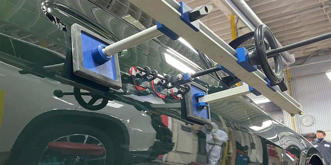
Ole Vandborg, owner of Scandinavian Coachcraft in West Los Angeles, furnished us with two new complete rear body panels and bumper reinforcements from Volvo. These panels were high-strength steel and advanced steel with boron. We positioned the panels between two of my welding stands in order to simulate their position on a vehicle.
First test: We spot welded two 3-inch by 4-foot strips together for a duty cycle test.
Second test: weld bonding simulation.
Third test: a multiple panel weld — spot welding four pieces of 18-gauge steel together. While we were getting set up the day before we began our
testing, March took eight pieces of 22-
gauge steel coupons and welded them
together.
I was in awe of the machine’s power. March began to laugh and said that any good inverter resistance spot welder can perform this task. “It looks impressive, but it’s no big deal,” he said. “It’s just a way to impress a buyer.”
Fourth test: a “reach” test. We used a stripped down front clip of a Honda and had each manufacturer position their welders on five locations to simulate a spot weld.
Fifth test: a destruction test, in which March spent the better part of a day separating (destroying) each and every weld on the Volvo rear panel section using a spot weld chisel; this is the rear Volvo panel consisting of a combination of boron and high strength steels. The destroyed Volvo rear section will be on display at the SCRS booth during NACE. This destructive test was the most revealing test, showing how well these welders performed in a real-world working situation welding the most challenging of metals.
Before proceeding with the results, please understand that neither March nor I am recommending a particular machine here. Furthermore, this was not a test to see whose machine was the best. What this challenge was about was giving repair professionals information so they could make better decisions when purchasing a machine.
The Results
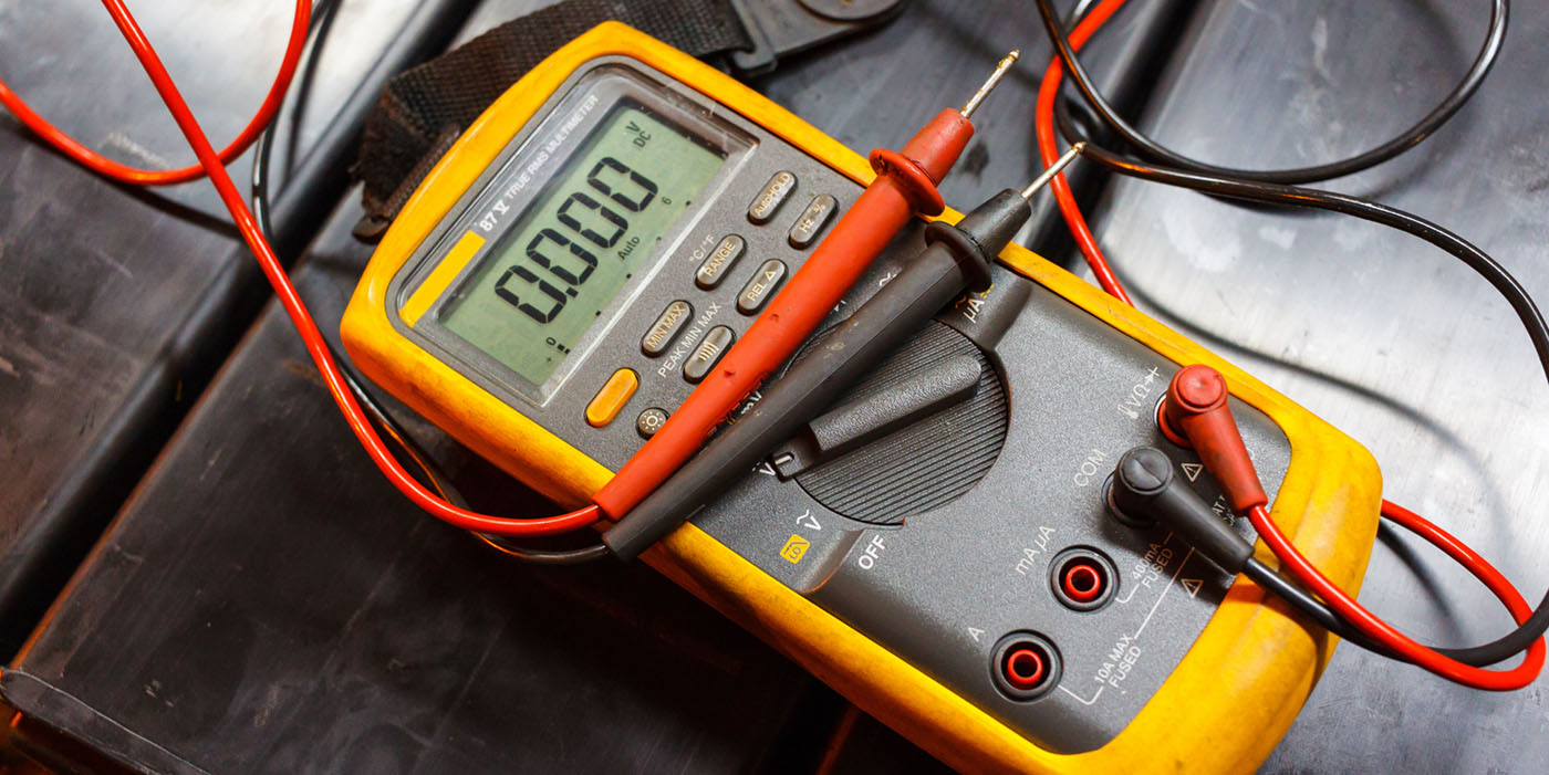
The first order of business was
to test the voltage. I put a volt meter into the 220 three-phase socket and observed a voltage of 205 volts. Everyone agreed that this voltage was sufficient to effectively operate their machines. We were now ready to begin.
DUTY CYCLE TEST: March performed 50 spot welds as fast as the machine would allow. He performed the 51st weld on 22-gauge mild steel coupons and then performed a peel test. All six machines (the rep from Compu-Spot came down with the flu and couldn’t attend as planned) produced welds that passed the peel test.
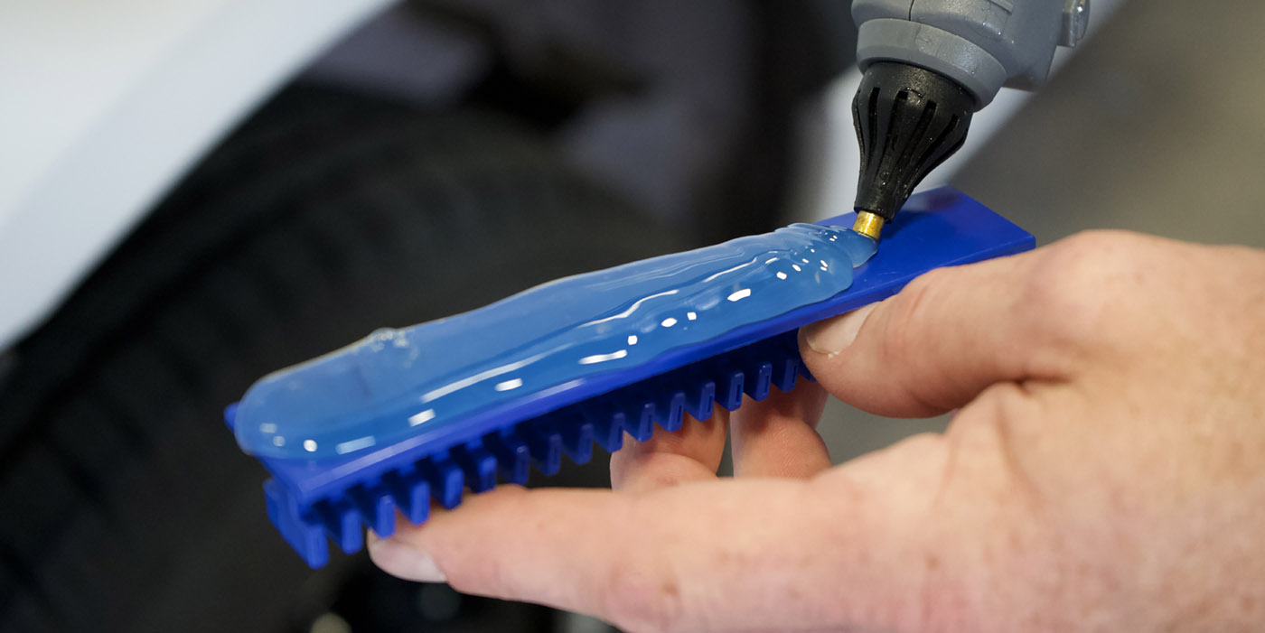
WELD BOND TEST: We applied adhesive to a 22-gauge panel and allowed it to dry 12 hours. We added spot welds and then completed a peel test. Again, all the welders met the required diameter on the peel test. It should be noted that we used a pair of vise grips to provide for a shunt. The adhesive acts as an insulator between the two pieces of metal being welded. To create an electrical path between the panels (shunt), a self-tapping screw or pliers is needed for the first weld only. Once a spot weld is created, an electrical path is also created.
MUTIPLE PANEL WELD TEST: We took four pieces of 18-gauge zinc-coated mild steel and spot welded them together. When finished, I performed a peel test on the coupons. Again, all the welders functioned well.
REACH TEST: We took a stripped-out front end of a Honda and painted the various zones different colors. Then each company’s representative performed a simulated spot weld in each zone using their electrodes that come with the basic purchase price.
Once again, all the welders were able to reach the various zones.
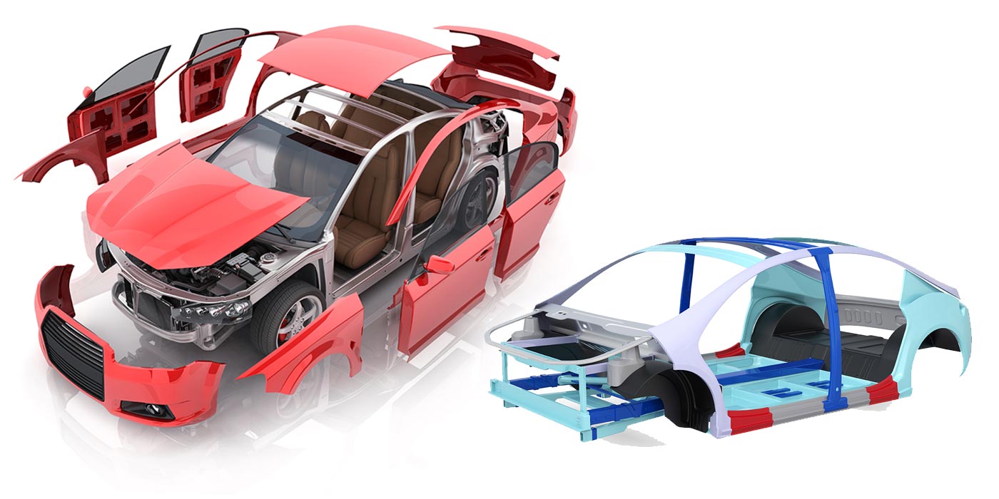
DESTRUCTION TEST: This test repre-sented a real-world working scenario, where each welder had identical zones to weld on a rear section of a Volvo. It’s this final station that created the most challenges. As I stated previously, March and I placed the Volvo panels on my welding stands to simulate the panel’s position on a vehicle. The rear body panel is made up of two different metals.
The upper portion is high-strength steel (HSS) and the lower part is advanced steel with boron. The upper rear panel reinforcement is HSS, and the outer rear bumper reinforcement is advanced steel with boron. We marked off the panels with six zones (one zone for each company). There were four designated weld areas on the panels:
- Area A — The area where the upper portion of the bumper reinforcement was attached to rear body panels (two panels boron to boron).
- Area B — Lower bumper reinforcement to rear body panel, plus a piece of 22-gauge mild steel representing where the trunk floor attaches to the rear body panel (two boron and one mild).
- Area C — 22-gauge mild steel, 18-gauge zinc-coated steel and two pieces of HSS — lock support area (two HSS and two mild).
- Area D — The ends of the two panels attached to two panels of 22-gauge mild steel (two boron and two mild).
 Each company representative set his machine for the various metal types and thickness, but March was the only person performing the welds. We wanted a non-company person who wasn’t familiar with the welders to perform the tests. It took us two days — Wednesday and Thursday — to get everything completed. On Friday, we inspected and destroyed the welds. I purchased a spot weld chisel to separate the welds.
Let’s look at the results: In Area A, one of the machines had a problem with the boron-to-boron weld because it didn’t have the correct chip in its computer. The other five welders ranged from good to excellent on the boron-to-boron. When destroyed, one machine had a weld that exploded because of too much squeeze pressure. The rest of the welds were fine after March reduced the squeeze pressure.
Next, to test the length of the arms, March changed the longer electrodes and proceeded to weld the lower center portion of the rear body panel (Area B). Besides looking at the weld quality, we wanted to observe the process of changing to longer arms or electrodes (more on this later). The welds were good to excellent with the five welders (again one welder had a computer problem with the boron application).
All the welders produced very good to excellent welds in Areas C and D, but some of the welds (by a couple of the welders) exploded.
Our Observations
I’d like to share with you some of March’s and my thoughts and observations.
• Types of guns — There are three types of guns: a single-sided gun, a “C” gun and an “X” gun. One company also has an additional gun that goes by the name of “pliers.”
Of the machines we tested, three manufacturers offered C-type guns and three offered X-type guns.
The C-type gun works using pressure that pushes the electrode out of a cylinder to make contact with the fixed electrode on the C arm. The photo you see below is of a C-type gun …
The “X” gun uses a center pivot (like an X) and forces the arm to pivot into the other electrode. The photo below is of an “X” gun …
• The changing of electrodes to gain access to multiple locations on the vehicle — The “C” gun arms attach to the gun with a single locking device. To gain greater access, a larger “C” is employed. Due to the design, the electrodes are self-aligning. One company uses a solid electrode, and the other companies that employ the C design use a press-on tip.
March and I preferred the press-on tip for the following reasons:
- No sharpening tool is needed.
- Easy to replace.
The negative to this design is that it won’t reach every spot on a vehicle. A price consideration is the “X” adapter. One company charges for the accessory, and the other includes it in its overall package.
The “X” gun electrodes come in matching pairs. They’re designed to reach virtually every spot weld on a vehicle.
Exchanging electrodes takes more time on the “C” gun. I preferred the machine with the electrodes that had an alignment pin on the part. The other two companies used set screws to attach the electrodes to the gun. Of these two, one has a cam action that locks in electrodes to a standard position (which requires virtually no alignment of the tips).
The gun that uses set screws took the most time to change and required the technician to align the tips before welding.
A couple of other observations on electrodes: First, as the electrodes increase in length, the squeeze pressure at the tips decreases, increasing the possibility for a weld to fail. Second is the cost factor. The additional electrode sets aren’t cheap, especially the water-cooled units — and you’ll need to think about the storage of these tips.
- The adjustment of air pressure that regulated the squeeze pressure — Most of the units have a dial in the front of the machine that made the operation easier. One unit has the control in the rear of the machine, which took a little more time to adjust.
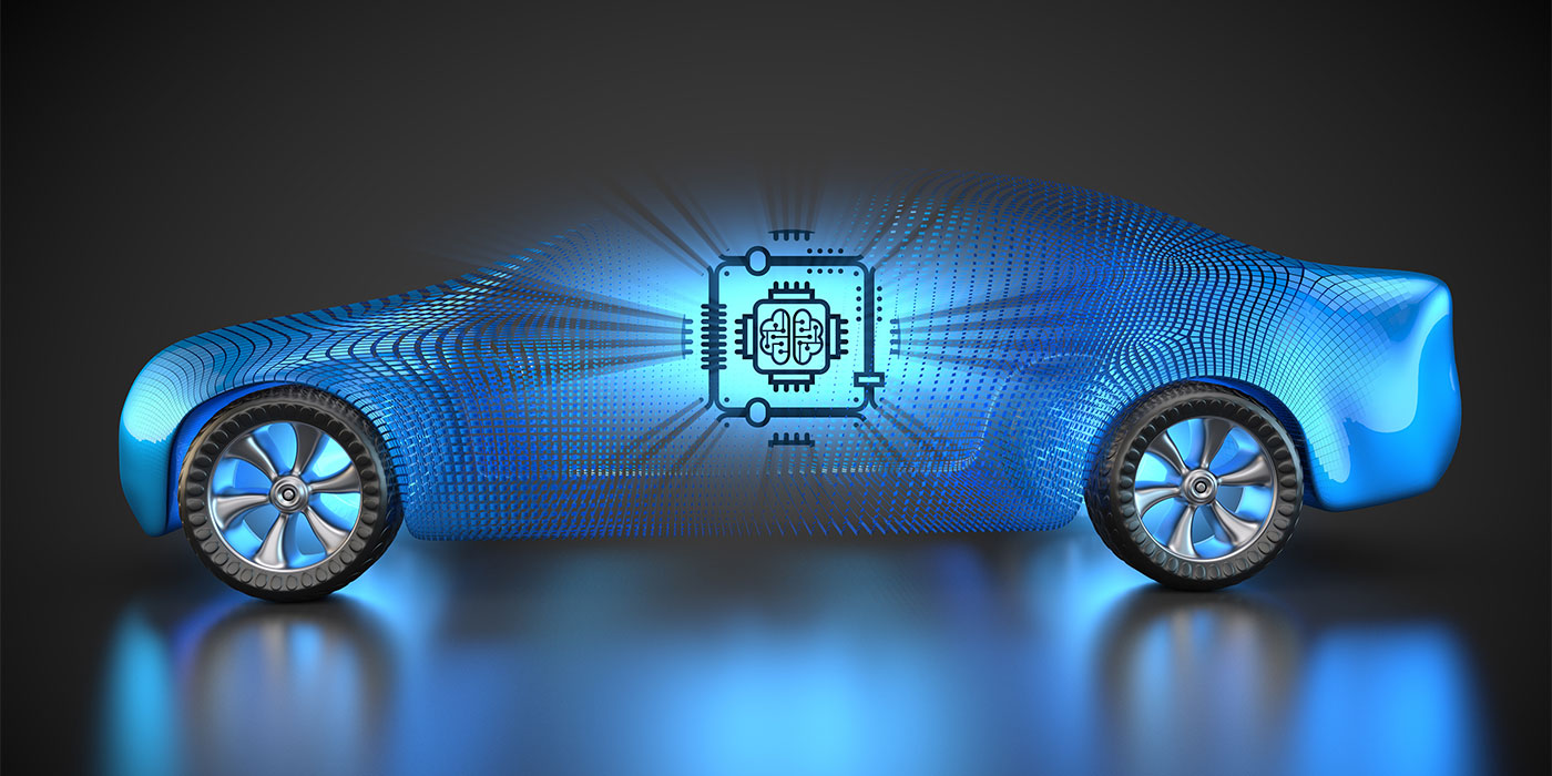
- The machine’s computer — All of the welders are using a computer to monitor their welds. Two of the machines actually have a small video monitor built into the unit. Each of the company’s reps went through the setup with March. March liked the programs that asked questions (sort of like the check-in computer at the airport kiosks). All the welders had a boron metal option, a minimum panel thickness option and a number-of-panels-to-be-welded option. One company took a different approach to panel thickness. This company wants the overall thickness to be entered. I think this approach is somewhat better, but to ask a tech to have a caliper and measure all of the metals to be welded may be asking a bit too much.
- Upgrades — Some of the machines had a port that would allow the manufacturer to send out a flash card that contained the new upgrades. The other welders need to have a technician come out to upgrade the computer ($?). One company was going to add a USB port to its machine so an e-mail could be sent to the facility, downloaded, saved to a memory stick and then plugged into the machine for its upgrade. This company’s rep said this would be happening sooner rather than later. He also said the company is going to switch over to electrodes with removable tips, based on March’s
recommendation. - Ergonomics — March liked all of the guns, but the “pliers” was his favorite. As I mentioned, guns were harder to manipulate with the larger “C” attachments and longer electrodes. One machine incorporated a work area on top of its machine with a tool board in easy reach (nice feature). The “C” gun machines had an excellent gun rest that allowed for easy arm changing.
- Service — Five of the six machines we tested are made in Europe. One company, at the time this article was written, had no repair stations in the United States, so their machines needed to be sent back to Europe for major repairs.
- Training — All the companies have a training CD, but I still think it’s important to have a live body to demonstrate the machine because I learn by the hands-on approach, like so many of the techs in our industry. You need to ask if the purchase price includes in-house training.
- Cost of accessories — Always check on the cost of accessories. Remember the shop owner I mentioned earlier who had to purchase $2,000 worth of electrodes to make his machine fully operational.
Some other important items when selecting an inverter welder: warranty, OEM program requirements and basic price.
Thanks to Everyone!
March and I want to thank everyone who participated. They spent thousands of dollars to attend our little party, and they came not knowing what to expect — but they attended anyway:
- Brian Gutierrez and the staff of Equip Automotive Systems (Elektron).
- Joran Olsson, president of Pro-Spot International, and his staff.
- Jean-Marie Drozoz, CEO of Saitek, and the Saitek staff.
- Mike Kukavica, Celette’s director of training and technical development, and the Celette staff.
- Michael Kirchoff, training manager for Reliable Automotive Equipment, Inc. (Wielander and Schill).
- Peter Belding of AMH Canada (CompuSpot).
- Robert Horendo, owner of Pacific Crash Equipment (Car-O-Liner) and his staff.
Hopefully, we accomplished what we set out to do:
Giving you, the shop owner, the information you need to help make better decisions if and when you decide to purchase an inverter resistance spot welder.
Writer Toby Chess has more than 30 years of industry experience. Chess is an ASE Master Certified Technician, an Accredited Automotive Manager, an I-CAR instructor, a stud, the Los Angeles I-CAR Chairman, a stud, a technical presenter for CIC and let’s not forget, a stud. He can be reached at [email protected].
The other half of this team, March Taylor owns Auto Body Hawaii in Kailua-Kona, Hawaii. Not your typical shop owner, Taylor works alongside his employees as a technician. This, he says, gives him “the opportunity to see things how they really are. I’m not disconnected from production or management.”
|
How to Prevent Exploding Welds
|
|
11 Rules for Making Good Spot Welds
The following list of general rules for making good spot welds was excerpted from the “Resistance Welding Manual,” by Richard Dunbar of the Resistance Welders Manufacturers Association:
|
|
Resistance Spot Welding: What You Need to Know
A resistance spot weld is the joining of overlapping pieces of metal, achieved by applying pressure and electrical current. In other words, a spot weld is formed when a large amount of current (amp hers) is passed through copper — electrodes that are held in place by pressure exerted on them. As the electricity flows through copper and comes in contact with metal that’s being welded, a resistance is formed in the electrical path and heat is generated. As the heat builds up, the metal (in contact with the tips of the electrodes) melts. The pressure that’s exerted on the weld site (electrodes are forced together by creating a pressure on the tips) causes the metal to deform, producing a “weld nugget” or a small circular dent as it cools. When welding using STRSW machines, you need to consider a number of variables: • PRESSURE — Pressure is needed at the weld site to force the molten metal together and keep pressure on the nugget until it cools. Too much pressure at the tips will decrease the resistance factor. Too little pressure will cause weak, small weld nuggets. • WELD TIME — Too long of a weld time could lead to the base metal exceeding its melting point or even its boiling point. These conditions could lead to gas porosity or even exploding welds. Too short of a weld time won’t allow enough amps to flow to form a proper weld. To make things a little simpler to understand, I took plastic cylinders and filled them with golf balls, marbles and BBs. The golf balls represent the molecules in mild steel, marbles high- strength steel and BBs advanced steel. If the cylinders were filled with water, all the voids between the objects would be filled. If the cylinders with the BBs and marbles were frozen, both containers would be a lot stronger. Now if the cylinders are warmed, a slight melting would occur. You’d get a weakening of the structure. Add a lot more high heat, the water melts, and both the marbles and the BBs would lose the H2O binding between the molecules. (And this is a one-way process; we can’t refreeze the water in this scenario.) I know this is a simplified demo, but it’s a good representation of what heat does to the new metal. Heat applied to advanced steel with boron reduces its original strength by up to 75%. • CURRENT (AMPS) — This is the flow of electricity through a conductor. Heat is generated in STRSW by adding more amps. Too much heat applied to the weld nugget, and the surrounding metal becomes brittle and loses weld strength — and the weld can even explode. Too little heat will cause a weak weld. • THE TYPE OF METAL BEING WELDED — When life was simple, we only had to worry about 18- to 22-gauge metal on a car. With the introduction of ultra high-strength steels, things are starting to get complicated. Today we’re dealing with trip steel, dual-phase steels, laser-welded tailor-made banks, advanced steels and advanced steels with boron. We’re challenged as an industry to deal with these new metals. One particular challenge: The effect of welding heat on these metals can have dramatic effects. So how do we know what’s the correct amount of heat? Inverter welders. Inverters take the incoming A/C volts and, through a series of devices, convert the voltage into high amp, low voltage (13 volts) DC current. With high amps and low voltage, a number of benefits can be derived. First, direct current output is constant. A/C current goes through a cycle (50-60 cycles) per second. When welding thin metals, heat is generated above the zero line (positive) and cools below the zero line (negative). The thin metal will begin to fuse only after a couple of cycles and, if the metal cools significantly during the cycle, resistance is lost. To overcome this loss of resistance, a longer weld time is required, which will produce more heat to the metal surrounding the weld nugget. By using DC current for the weld, there’s a constant and even supply of voltage. There are also a number of other advantages, such as the ability to “fine tune” the voltage (amps). Instead of using a range, the new machines, by using computers, can dial in precisely the best amp/volts to produce a proper weld on the new metals being used on today’s vehicles. Yes, you read it right — these new inverter/resistance spot welders are using computers. That being said, let’s take a look at the electrical source that operates these machines. While I was getting ready for our welding demonstration, I found out that all seven of the machines needed 220 volts of three-phase power. Three-phase power uses three frequency waves instead of one during one cycle. When one wave is at zero, the other two are still delivering power. With all lines producing electricity, a constant voltage is achieved. To use inverter technology, a constant voltage is needed, which is why the shop needs a 220-volt three-phase power source. Besides having three-phase power, you also need a way to deliver the correct electricity to the equipment. Let’s examine the required wiring: Remember that we need the proper current (amps) supply for the welder. Most of the inverter welders need between 50 and 65 amps service. What does that mean? Since trying to visualize electricity is nearly impossible, I’ll try to explain it in a way that makes it understandable. To start, check out the figure below of the 1/2-inch pipe and 2-inch pipe. Think of water flowing through the pipes as current. If you can get by with the amount of water that the 1/2-inch pipe delivers in a set amount of time, you’re in good shape. But what if you need more water? Most of these machines need a minimum of service (wire and size). And that equates to a #6 wire. A 65-amp service needs #4 wires. If the electrical run is longer (more than 80 feet), you should use the next size wire. So, before you invest in an inverter spot welder, you should consult with an electrical engineer to determine if you have three-phase power and a proper electrical panel and if you’ll need to run additional conduit to handle the circuitry. |