Is carbon fiber structural repair really black magic? The answer, of course, is no. It’s true that carbon fiber structural components such as “tubs” are a relatively new technology for high-volume production street cars, but structures like tubs have been used in Formula 1 racing since the early 1990s and in heavily loaded aircraft structures since the 1970s. Repair techniques have been developed and thoroughly tested in the aircraft industry by large organizations such as Boeing and have been validated by the Federal Aviation Administration. And they work!
Flying High
Thousands of these types of repairs are performed every year in the aircraft world, often in a fairly short time (a few hours), and have an excellent record. They’re not difficult repairs in most cases, and are not more difficult to perform than, say, welded repairs on steel structures.
However, the techniques, materials and equipment are quite different than those for metal structures. In some ways, working with composite structures uses skills more common to cabinet makers than metal workers.
Repair or Replace?
Some automakers using carbon fiber have decided that if body panels are damaged beyond the point of a “cosmetic” repair, they should be replaced rather than repaired. The difference is whether the body panel is painted or not.
While it’s possible to repair a painted carbon fiber body panel and get a “Class A” finish once repainted, that’s not possible on an unpainted carbon fiber panel – the repair will always be visible. However, the same can be said for repaired aluminum body panels that are left unpainted.
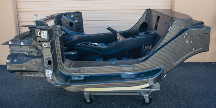
The tub (above photo) is the carbon fiber structure to which the engine, transmission, suspension, interior and body panels are attached. It’s the “chassis” in many new designs. If this structure gets heavily damaged in a severe accident, the insurance company is likely to declare the vehicle a total loss and no repairs would be necessary.
If the tub is less severely damaged, especially on a very expensive car, then a repair would likely be performed, and your shop may be asked to do the repair.
Step by Step
Repairs to carbon fiber structures follow a predictable set of steps, although the complexity of the damage can change the number of individual steps needed. The following example assumes a simple repair to a set of delaminated outer plies on a structural surface with no actual puncture or through-hole damage, and no damage to underlying honeycomb or foam core.
- Step 1 – Remove body panels and other items to gain access to the repair area, for at least one extra foot all around the visible damage if possible. It will be helpful if backside access to the damaged area is available.
- Step 2 – Inspect the damage to determine its actual size. Carbon fiber is a brittle material. While it may be crushed in, it will not bend and stay bent like metals. The actual damaged area, including cracks in the resin, delaminations between layers, etc., often extends well beyond the visible damage. The extent of the “hidden damage” is very important to know and will determine the size of the eventual repair. Determining the size of the hidden damage is usually performed by “tap testing” using a simple small lightweight tap hammer or even a quarter. An undamaged area, when lightly tapped, should have a sharp, almost metallic ring tone. A damaged area will have a duller “thud” sound. Tap in an organized pattern around the visible damage, every inch or so, marking the area where the tone just begins to change from a sharp rap to a dull thud. A silver Sharpie felt tip pen works well for marking out the area of damage, which may be significantly larger than the visible damage. Note: other methods of non-destructive inspection utilizing ultrasonic phased array, thermography or other techniques may be required for determining damage in thicker laminates or for larger, more complex damage repairs not covered in this article.
- Step 3 – Thoroughly clean the area to be repaired using clean rags and isopropyl alcohol or acetone, removing any dirt, grease, oil, road grime, etc. Remove the damaged cloth layers (plies) using a die grinder with 80 grit or finer sanding discs. All damaged, crushed fibers or delaminated plies of cloth, etc., must be removed down to the original undamaged materials.
- Step 4 – Taper sand (often called scarfing) back from the middle of the damage removal area, using 1/2 inch per ply taper angle. So if you’re scarfing through four plies, then a minimum four-inch-wide scarfed area would be needed, two inches all the way around from the middle of the damaged area, plus the dimensions of the damage itself. For example, a six-inch wide delaminated area in this four-ply structure would result in a 10-inch-wide tapered scarf. Scarfing technique, like much bodywork, is a muscle “motor skill” that needs practice, but it’s not really difficult, and practicing on scrap panels is pretty easy to do. One hour or so of practice is all that’s needed for most people. Appropriate personal protective equipment such as a good quality N95-rated dust mask and eye protection are needed for taper sanding.
- Step 5 – Clean the scarfed surface as before, removing all dust and grit. Trace the outlines of the visible edges of each ply in the scarfed area, ply by ply, on a thin sheet of clear plastic with a Sharpie pen. You will use these tracing templates for the layout of the repair plies. Important: mark the ply orientation (direction) of the fibers on each template.
- Step 6 – Obtain a piece of carbon fiber cloth large enough to cut all of the required repair plies. Place the fabric between two sheets of thin clear plastic film, taking care so as not to distort the fiber. Using the tracing templates, mark each ply and fiber orientation on the top side of the film. In our example, four repair plies would be needed. If the scarfed area is circular, around a six-inch-wide damaged area, then 7-inch, 8-inch, 9-inch and 10-inch diameter plies would be needed. If the scarfed area is not a perfect circle, then each repair ply will need to match the ply shape and orientation of the original structural plies. This is very important! If possible, these repair plies should be made from the same type of carbon fiber cloth as used in the original structure, as specified by the manufacturer of the vehicle.
- Step 7 – Mix an appropriate amount of epoxy repair resin, typically about the same weight of mixed resin as the weight of the cut-out cloth, plus a little extra for waste. Always use epoxy resin (not polyester resin or vinyl ester resin) for structural, load-carrying carbon fiber repairs. As with the cloth, the exact type of epoxy to be used should be specified or approved by the vehicle manufacturer. Carefully mix the resin in clean plastic cups, not waxed paper cups, and mix at the exact ratio of resin and hardener as specified by the resin vendor. Mix ratio with epoxies is critical; if you’re off by more than 2 percent, the resin will never gain full strength. You cannot mix by “eye”; you must mix accurately.
- Step 8 – Saturate the carbon fabric with the freshly mixed resin by placing half of the mixed resin and the dry cloth on the first sheet of plastic film, and pour the remaining resin on top of the cloth, placing the (ply-traced) piece of clear film over the top. Use a plastic or rubber squeegee to work the resin through the cloth, saturating all the way through. Squeeze out any air bubbles and excess resin, and then flip the plastic over to look at the backside. Squeeze out any air bubbles on the back until the cloth is evenly saturated on both sides and there are no remaining dry spots or air bubbles. Cut each repair ply as marked from the film-covered fabric. Leave the plastic film in place until just prior to application in the repair.
- Step 9 – Using a small paint brush or acid brush, paint on an “interface coat” of freshly mixed resin over the entire scarfed area. Then, remove the bottom layer of film and apply the first repair ply to the repair area. (Note: the small ply goes down first). Carefully remove the film from the first repair ply before proceeding with the next repair ply. Carefully orient the fibers in this ply to match the fiber orientation of the original structure, which you marked on the tracing templates in Step 5. (We mentioned that marking the orientation was important!) (See photo below)
- Step 10 – Apply the remaining plies (in our example, there will be three remaining at this time) over the repair area as before, taking care to orient each ply to match the original structural plies. You will work from smaller to bigger repair plies, with the biggest ply on top. Carefully and gently squeegee each ply into place, squeezing out any air bubbles or wrinkles. Be sure to remove all plastic film from each layer in the process and save to verify that all film was removed from the repair.

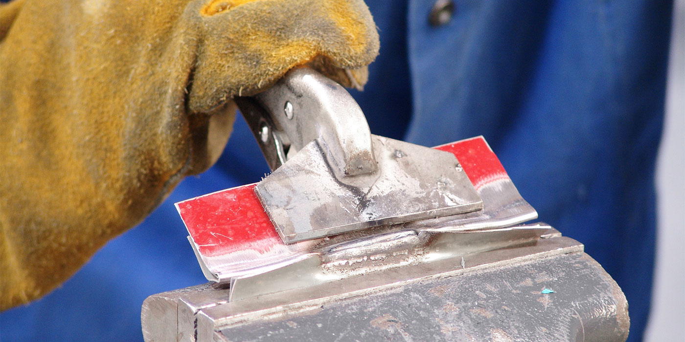
An example of a scarfed repair, which involves taper sanding. - Step 11 – Cure the repair area. There are some epoxy resins which will cure at room temperature, although this can take days if the temperature is cool. Most of the strong structural wet lay-up repair resins require an elevated-temperature cure. This is typically done somewhere between 140°F and 200°F for a few hours. The heat can be applied by a hot air blower into a temporary aluminum foil tent built over the repair, or with a heat blanket or other controlled heat source. However, these resins systems will give their best strength if they’re vacuum-bagged prior to cure, as in Step 12.
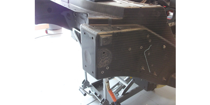
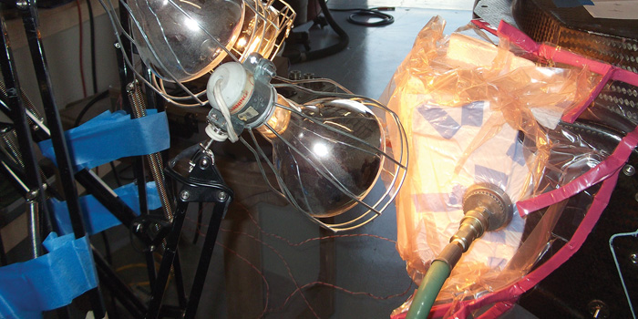
- Step 12 – Vacuum-bagging the repair patch (see photo below) is the preferred method used for obtaining the best results. The purpose of the vacuum bag is to pull out the thousands of tiny air bubbles from the uncured resin, which can be trapped in the weave of the cloth and between plies. Every place there is a tiny air bubble means there is not a bond between the resin and the cloth, which weakens the entire structure. The vacuum bag also squeezes the plies together and presses the repair against the original structure, helping to ensure a good bond. By pulling all the air out of the vacuum bag with a vacuum pump, atmospheric pressure pushes on the repair area. At sea level with a good vacuum pump, more than 14 pounds per square inch can be achieved. For example, a bag on a one-square-foot repair amounts to slightly more than 2,000 pounds of compaction pressure on the repair! This can be obtained with the same type of vacuum pump as is often used in auto air conditioning work. There are thin layers which need to go inside the vacuum bag, over the repair to “bleed” excess resin out of the repair plies, “breathe” the air out, and serve as “release” layers to keep the bleeder and breather layers from sticking to the patch. The vacuum bag itself is a nylon film which goes on top of the other layers and is typically attached to the structure with a sticky, thick vacuum-bag sealant tape. Full vacuum is applied to the bag until the repair is cured.
- Step 13 – The last step! All that’s left is de-bagging the cured repair, tap-testing the surface to make sure there are no bonding problems, light surface smoothing with a fine abrasive pad, admiring your handiwork, and then cleaning and painting.

Vacuum-bagging the repair patch pulls out air bubbles from the uncured resin and also helps ensure a good bond.
Summary
While there are a lot of steps, each one individually is not particularly difficult or time-consuming. As mentioned at the top of the article, many thousands of these repairs are performed every year already in the aircraft industry, with an excellent track record. While the steps described provide a basic outline of what needs to be done, this article in no way actually prepares anyone to go perform such repairs. There are many vital details omitted due to lack of space, such as health and safety requirements, exact choice of resins and repair cloth, mix ratios, cure time and temperature cycles, vacuum bagging details, etc.
At the current time in the automotive industry, carbon fiber repair is a relatively small but rapidly growing area, as more and more auto manufacturers are embracing carbon fiber structures as a path to more fuel-efficient vehicles. Even electric cars are going to these lightweight yet strong materials to help compensate for the relatively heavy batteries.
However, the numerous details mentioned above really do make a genuine difference in the strength of the repair. Also, trying to repair an automotive tub structure may require full restoration of its original, energy-absorbing characteristics in a crash, as well as restoring its shape and function. You need to get it right!
The only way to learn these repair technique details is to obtain good hands-on training, which is now a “must-have” for success in this field. Don’t delay – get in on the ground floor, become the first in your area to develop expertise and you’ll become known as the “go-to” shop for these repairs!