This article is the sixth in a series on battery electric vehicles (BEVs) and hybrid electric vehicles (HEVs).
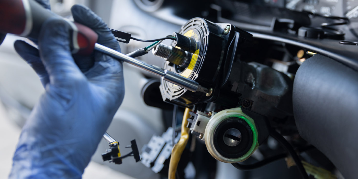
High-voltage (HV) systems in today’s electric vehicles (EVs) have vast amounts of power to efficiently propel a car down the road, but storing and using all that power has certain inherent risks. Although generally safe to the owner or operator of the vehicle, the HV system poses more risks to the service or collision repair technician who performs work on the vehicle. In this article, we’ll take a look some of the safety systems commonly used in HV systems.
Insulation Guard
An insulation guard is a function of the HV battery control unit. The control unit monitors the overall battery performance and identifies when the battery contactors are closed, allowing the battery to supply power to the HV system. If one or more components in the HV system has an electrical leak, for example, to the component housing, an “insulation error” occurs – and that is a dangerous situation. The insulation guard will detect this error and typically put a warning on the instrument panel or center display. When this happens, the battery control unit will disable the HV system and the vehicle will not be able to be driven.
It is important to note that in order for the insulation guard to test the system properly, all HV components must be bonded, which means they have a good connection to the vehicle chassis. The insulation resistance is measured over the chassis to each HV component. If bonded correctly, an HV component will have a low ohm reading in the area of milliohms. If resistance is too high, the component will not be included in the insulation guard measurement and a fault will not be detected. In this scenario, a component could be faulty, but the battery control unit would not be able to recognize this and would fail to shut down the HV system and disable the vehicle.
High-Voltage Interlock Loop
The interlock loop is a 12-volt, low-current safety interlock (integrity) loop circuit. These safety loop circuits tie in with all HV connectors, harnesses and other system parts. If a fault is detected within the safety loop circuit, or if a cover or connector is removed, the 12-volt loop is interrupted and the main battery contactors will immediately open up, removing power from the HV system and isolating the battery. If the contactors are already open when this loop is interrupted, the contactors are not allowed to close. Think of a contactor as a typical electrical relay: add the 12-volt current and the relay circuit closes, remove the 12-volt current and the relay circuit opens.
Active/Passage Discharge
The HV invertor contains high-voltage capacitors. A capacitor is an electrical storage device. In an HV system, the capacitor will typically store the same voltage as the HV battery. When AC (alternating current) is converted to DC (direct current) via a rectifier circuit, the converted DC current is unstable and not in a perfect state to be stored in the battery. To stabilize this voltage, the system uses capacitors. The power stored in the capacitor must be discharged (drained) for technician safety when working on an HV system. There are two ways of removing power from the capacitor, active and passive discharging.
Active discharge has a low ohm switched resistor wired parallel to the capacitor. When the ignition is turned off, the switch on the resistor closes, completing a circuit and causing the capacitor to drain in a matter of a few seconds. It is the low resistance (ohms) that allows the quick discharge of the capacitor. It is called active because the circuit needs to be deliberately or actively closed in order to allow the capacitor to discharge.
Passive discharge has a high ohm resistor wired parallel to the capacitor but has no switch; it is always a closed circuit. This high resistance slows down the discharge rate. Because the resistor has no switch and the circuit is always closed, it is always putting a drain on the capacitor. Due to the high resistance (slow discharge rate), the capacitor is not affected and is fully charged as long as there is power going to the inverter. Once the power is shut off to the invertor, the capacitor begins to discharge.
Always refer to vehicle-specific OEM HV disconnecting procedures to verify the required capacitor discharge time. With passive discharge, there is no switching to complete the circuit of the resistor, and the resistor circuit is closed at all times. This means there is far less chance of a fault preventing a capacitor to discharge.
HV Battery Contactors
An HV battery contactor is basically a more heavy-duty version of a relay. An HV battery has three contactors inside it. As with any electrical switch, an electrical arc can be created when closing a circuit. The higher the voltage, the stronger the arc and the greater distance it can “jump.” With HV batteries, the power is great enough to cause a risk of fire or fusing of the contactor’s contacts. Every time you turn the ignition on and off in an HV vehicle, you run the risk of creating an electrical arc.
To prevent this arc from occurring, a resistor is used to increase HV system safety. When the ignition is turned on, the first of the three contactors close. Since this is the first contactor to close and the circuit is still open, there is no power to create an arc. The second contactor, called a pre-charge contactor, will complete the circuit, but it has the high ohm resistor that reduces the voltage to a level low enough that it will not create an arc as the contactor is closing. This then allows the third contactor to close without risk of an arc as the circuit is already closed but with reduced power. Once the third contactor closes, the circuit has full power as the path of least resistance is taken. At this point, the current sensor module recognizes that the circuit is closed with full power and it signals to open the second contactor (pre-charge), as the path with the resister is no longer needed.
HV Battery Thermal Management System
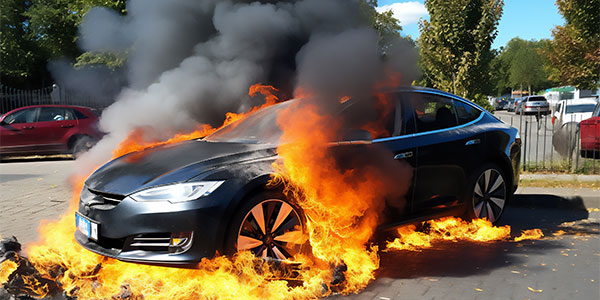
Controlling the temperature of an HV battery is important for safety and long life. The ideal temperature is about 77 degrees Fahrenheit or 25 degrees Celsius. At low temperatures, the chemical process in the battery is slowed down, thus reducing energy and performance capability. At excessive high temperatures, similar effects take place and – in rare and extreme cases – very high temperatures can cause thermal runaway, which can lead to a battery fire.
At the ideal temperature of 77 F, a fully charged battery is at 3.6 volts in each cell. However, as temperatures deviate from this ideal, especially when it is an extreme deviation, individual cells do not all react the same and there will be variations in cell voltage. It is important that each battery cell voltage is balanced with one another. The battery control unit works to maintain the same voltage and the ideal temperature in the individual cells.
A battery heater is used to warm the battery as needed, and a coolant- or refrigerant-based cooling system is used to cool it. Some HV batteries utilize both cooling systems. These systems require power to operate, and at least some if not all of that power will come from the HV battery. On a cold winter night, with the HV-powered vehicle off and parked, the battery heater will operate to maintain 77 F, which will consume a fair amount of energy from the HV battery. It is not uncommon for an HV battery to lose 10 to 15% of its power overnight to keep the battery at the optimal temperature.
Summary
Knowing and understanding the safety systems that are used on HV vehicles is not only important for safety but to help ensure a complete, safe and quality repairs.